TOSCA Simple Profile for
Network Functions Virtualization (NFV) Version 1.0
Committee Specification Draft 03
17 March 2016
Specification URIs
This version:
http://docs.oasis-open.org/tosca/tosca-nfv/v1.0/csd03/tosca-nfv-v1.0-csd03.pdf (Authoritative)
http://docs.oasis-open.org/tosca/tosca-nfv/v1.0/csd03/tosca-nfv-v1.0-csd03.html
http://docs.oasis-open.org/tosca/tosca-nfv/v1.0/csd03/tosca-nfv-v1.0-csd03.doc
Previous version:
http://docs.oasis-open.org/tosca/tosca-nfv/v1.0/csd02/tosca-nfv-v1.0-csd02.pdf (Authoritative)
http://docs.oasis-open.org/tosca/tosca-nfv/v1.0/csd02/tosca-nfv-v1.0-csd02.html
http://docs.oasis-open.org/tosca/tosca-nfv/v1.0/csd02/tosca-nfv-v1.0-csd02.doc
Latest version:
http://docs.oasis-open.org/tosca/tosca-nfv/v1.0/tosca-nfv-v1.0.pdf (Authoritative)
http://docs.oasis-open.org/tosca/tosca-nfv/v1.0/tosca-nfv-v1.0.html
http://docs.oasis-open.org/tosca/tosca-nfv/v1.0/tosca-nfv-v1.0.doc
Technical Committee:
OASIS Topology and
Orchestration Specification for Cloud Applications (TOSCA) TC
Chairs:
Paul Lipton (paul.lipton@ca.com), CA Technologies
Simon Moser (smoser@de.ibm.com), IBM
Editor:
Shitao Li (lishitao@huawei.com),
Huawei Technologies Co., Ltd.
Related work:
This specification is related to:
·
Topology and Orchestration Specification for Cloud
Applications Version 1.0. Edited by Derek Palma and Thomas Spatzier. 25
November 2013. OASIS Standard. Latest version: http://docs.oasis-open.org/tosca/TOSCA/v1.0/TOSCA-v1.0.html.
Declared XML namespaces:
·
http://docs.oasis-open.org/tosca/ns/simple/yaml/1.0/nfv/1.0/
Abstract:
The TOSCA NFV profile specifies a Network Functions
Virtualisation (NFV) specific data model using TOSCA language.
Status:
This document was last revised or approved by the OASIS
Topology and Orchestration Specification for Cloud Applications (TOSCA) TC on
the above date. The level of approval is also listed above. Check the “Latest version”
location noted above for possible later revisions of this document. Any other
numbered Versions and other technical work produced by the Technical Committee
(TC) are listed at https://www.oasis-open.org/committees/tc_home.php?wg_abbrev=tosca#technical.
TC members should send comments on this specification to the
TC’s email list. Others should send comments to the TC’s public comment list,
after subscribing to it by following the instructions at the “Send
A Comment” button on the TC’s web page at https://www.oasis-open.org/committees/tosca/.
For information on whether any patents have been disclosed
that may be essential to implementing this specification, and any offers of
patent licensing terms, please refer to the Intellectual Property Rights
section of the TC’s web page (https://www.oasis-open.org/committees/tosca/ipr.php).
Citation format:
When referencing this specification the following citation
format should be used:
[TOSCA-Simple-Profile-NFV-v1.0]
TOSCA Simple Profile for Network Functions Virtualization
(NFV) Version 1.0. Edited by Shitao Li. 17 March 2016. OASIS Committee
Specification Draft 03. http://docs.oasis-open.org/tosca/tosca-nfv/v1.0/csd03/tosca-nfv-v1.0-csd03.html.
Latest version: http://docs.oasis-open.org/tosca/tosca-nfv/v1.0/tosca-nfv-v1.0.html.
Copyright © OASIS Open 2016. All Rights Reserved.
All capitalized terms in the following text have the
meanings assigned to them in the OASIS Intellectual Property Rights Policy (the
"OASIS IPR Policy"). The full Policy may be
found at the OASIS website.
This document and translations of it may be copied and furnished
to others, and derivative works that comment on or otherwise explain it or
assist in its implementation may be prepared, copied, published, and
distributed, in whole or in part, without restriction of any kind, provided
that the above copyright notice and this section are included on all such
copies and derivative works. However, this document itself may not be modified
in any way, including by removing the copyright notice or references to OASIS,
except as needed for the purpose of developing any document or deliverable
produced by an OASIS Technical Committee (in which case the rules applicable to
copyrights, as set forth in the OASIS IPR Policy, must be followed) or as
required to translate it into languages other than English.
The limited permissions granted above are perpetual and will
not be revoked by OASIS or its successors or assigns.
This document and the information contained herein is
provided on an "AS IS" basis and OASIS DISCLAIMS ALL WARRANTIES,
EXPRESS OR IMPLIED, INCLUDING BUT NOT LIMITED TO ANY WARRANTY THAT THE USE OF
THE INFORMATION HEREIN WILL NOT INFRINGE ANY OWNERSHIP RIGHTS OR ANY IMPLIED
WARRANTIES OF MERCHANTABILITY OR FITNESS FOR A PARTICULAR PURPOSE.
OASIS requests that any OASIS Party or any other party that
believes it has patent claims that would necessarily be infringed by
implementations of this OASIS Committee Specification or OASIS Standard, to
notify OASIS TC Administrator and provide an indication of its willingness to
grant patent licenses to such patent claims in a manner consistent with the IPR
Mode of the OASIS Technical Committee that produced this specification.
OASIS invites any party to contact the OASIS TC
Administrator if it is aware of a claim of ownership of any patent claims that
would necessarily be infringed by implementations of this specification by a
patent holder that is not willing to provide a license to such patent claims in
a manner consistent with the IPR Mode of the OASIS Technical Committee that
produced this specification. OASIS may include such claims on its website, but
disclaims any obligation to do so.
OASIS takes no position regarding the validity or scope of
any intellectual property or other rights that might be claimed to pertain to
the implementation or use of the technology described in this document or the
extent to which any license under such rights might or might not be available;
neither does it represent that it has made any effort to identify any such
rights. Information on OASIS' procedures with respect to rights in any document
or deliverable produced by an OASIS Technical Committee can be found on the
OASIS website. Copies of claims of rights made available for publication and
any assurances of licenses to be made available, or the result of an attempt
made to obtain a general license or permission for the use of such proprietary
rights by implementers or users of this OASIS Committee Specification or OASIS
Standard, can be obtained from the OASIS TC Administrator. OASIS makes no
representation that any information or list of intellectual property rights
will at any time be complete, or that any claims in such list are, in fact,
Essential Claims.
The name "OASIS" is a trademark of OASIS, the owner and developer of this
specification, and should be used only to refer to the organization and its
official outputs. OASIS welcomes reference to, and implementation and use of,
specifications, while reserving the right to enforce its marks against
misleading uses. Please see https://www.oasis-open.org/policies-guidelines/trademark
for above guidance.
1 Introduction. 6
1.1
Terminology. 6
1.2
Normative References. 6
2 Summary
of key TOSCA concepts. 7
3 NFV
Overview. 8
3.1 Network
Services. 8
3.2 Network
Connectivity Topology. 8
4 Deployment
Template in NFV. 10
5 General
Mapping between TOSCA and NFV Deployment Template. 11
6 TOSCA
Data Model for a network service. 12
6.1
Namespace and Alias. 13
7 TOSCA
Data Model for a VNF. 14
8 TOSCA
template for VNFD.. 15
8.1 Node
Template Substitution Mapping for a VNF. 15
8.2
Capability Types. 18
8.2.1
tosca.capabilities.Compute.Container.Architecture. 18
8.2.2
tosca.capabilites.nfv.VirtualBindable. 19
8.2.3
tosca.capabilities.nfv.Metric. 19
8.3 Data
Types. 20
8.3.1
tosca.datatypes.compute.Container.Architecture.CPUAllocation. 20
8.3.2
tosca.datatypes.compute.Container.Architecture.NUMA. 20
8.4
Relationship Types. 21
8.4.1
tosca.relationships.nfv.VirtualBindsTo. 21
8.4.2
tosca.relationships.nfv.Monitor 21
8.5 Node
Types. 22
8.5.1 tosca.nodes.nfv.VNF. 22
8.5.2 tosca.nodes.nfv.VDU. 22
8.5.3 file: vdu1.image tosca.nodes.nfv.CP. 24
9 TOSCA
template for VLD.. 26
9.1
tosca.nodes.nfv.VL. 26
9.1.1
Properties. 26
9.1.2
Attributes. 26
9.1.3
Definition. 26
9.1.4
Additional Requirement 26
9.2 tosca.nodes.nfv.VL.ELine. 26
9.3 tosca.nodes.nfv.VL.ELAN. 27
9.4 tosca.nodes.nfv.VL.ETree. 27
10 TOSCA
template for VNFFGD.. 28
10.1
Semantics of VNFFG.. 28
10.2
Semantics of Network forwarding path. 28
10.3
Capability Types. 29
10.3.1
tosca.capabilites.nfv.Forwarder 29
10.4
Relationship Types. 29
10.4.1
tosca.relationships.nfv.ForwardsTo. 29
10.5 Node
Types. 30
10.5.1 tosca.nodes.nfv.FP. 30
10.5.2
Properties. 30
10.5.3
Attributes. 30
10.5.4
Definition. 30
10.6 Group
types. 31
10.6.1
tosca.groups.nfv.VNFFG.. 31
10.6.2
Properties. 31
10.6.3
Attributes. 31
10.6.4
Definition. 31
11 TOSCA
template for NSD.. 33
11.1
Metadata keynames. 33
11.2 Using
service template for a NFV network service. 33
11.3
Capability types. 38
11.3.1
tosca.capabilities.nfv.VirtualLinkable. 38
11.4
Relationship Types. 38
11.4.1
tosca.relationships.nfv.VirtualLinksTo. 38
12 Examples. 39
12.1 Simple
Virtual Router VNFD Template. 39
12.2 Virtual
Router VNFD Template with Efficient CPU placement properties. 41
12.3
Multi-VDU Virtual Router VNFD Template. 43
Appendix A.
Acknowledgments. 48
Appendix B.
Revision History. 49
The TOSCA NFV profile specifies a NFV specific data model
using TOSCA language. Network Functions
Virtualisation aims to transform the way that network operators architect
networks by evolving standard IT virtualisation technology to consolidate many
network equipment types onto industry standard high volume servers, switches
and storage, which could be located in Datacentres, Network Nodes and in the
end user premises.
The deployment and operational behavior requirements of each
Network Service in NFV is captured in a deployment template, and stored during
the Network Service on-boarding process in a catalogue, for future selection
for instantiation. This profile using TOSCA as the deployment template in NFV,
and defines the NFV specific types to fulfill the NFV requirements. This
profile also gives the general rules when TOSCA used as the deployment template
in NFV.
The key words “MUST”, “MUST NOT”, “REQUIRED”, “SHALL”, “SHALL
NOT”, “SHOULD”, “SHOULD NOT”, “RECOMMENDED”, “MAY”, and “OPTIONAL” in this
document are to be interpreted as described in [RFC2119].
[RFC2119] Bradner,
S., “Key words for use in RFCs to Indicate Requirement Levels”, BCP 14, RFC
2119, March 1997. http://www.ietf.org/rfc/rfc2119.txt.
[ETSI
GS NFV-MAN 001 v1.1.1] Network
Functions Virtualisation (NFV); Management and Orchestration
[TOSCA-1.0] Topology
and Orchestration Topology and Orchestration Specification for Cloud
Applications (TOSCA) Version 1.0, an OASIS Standard, 25 November 2013, http://docs.oasis-open.org/tosca/TOSCA/v1.0/os/TOSCA-v1.0-os.pdf
[TOSCA-Simple-Profile-YAML] TOSCA
Simple Profile in YAML Version 1.0
The TOSCA metamodel uses the concept of service templates to
describe cloud workloads as a topology template, which is a graph of node
templates modeling the components a workload is made up of and as relationship
templates modeling the relations between those components. TOSCA further
provides a type system of node types to describe the possible building blocks
for constructing a service template, as well as relationship type to describe
possible kinds of relations. Both node and relationship types may define
lifecycle operations to implement the behavior an orchestration engine can
invoke when instantiating a service template. For example, a node type for some
software product might provide a ‘create’ operation to handle the creation of
an instance of a component at runtime, or a ‘start’ or ‘stop’ operation to
handle a start or stop event triggered by an orchestration engine. Those
lifecycle operations are backed by implementation artifacts such as scripts or
Chef recipes that implement the actual behavior.
An orchestration engine processing a TOSCA service template
uses the mentioned lifecycle operations to instantiate single components at
runtime, and it uses the relationship between components to derive the order of
component instantiation. For example, during the instantiation of a two-tier
application that includes a web application that depends on a database, an
orchestration engine would first invoke the ‘create’ operation on the database
component to install and configure the database, and it would then invoke the
‘create’ operation of the web application to install and configure the
application (which includes configuration of the database connection).
The TOSCA simple profile assumes a number of base types
(node types and relationship types) to be supported by each compliant
environment such as a ‘Compute’ node type, a ‘Network’ node type or a generic
‘Database’ node type. Furthermore, it is envisioned that a large number of
additional types for use in service templates will be defined by a community
over time. Therefore, template authors in many cases will not have to define
types themselves but can simply start writing service templates that use
existing types. In addition, the simple profile will provide means for easily
customizing existing types, for example by providing a customized ‘create’
script for some software.
Network Functions Virtualization (NFV) leverages standard IT
virtualization technology to enable rapid service innovation for Network
Operators and Service Providers. Most current networks are comprised of diverse
network appliances that are connected—or chained--in a specific way to achieve
the desired network service functionality. NFV aims to replace these network
appliances with virtualized network functions that can be consolidated onto
industry-standard high volume servers, switches and storage, which could be
located in data centers, network nodes, or in the end-user premises. These
virtual network functions can then be combined using dynamic methods—rather
than just static ones—to create and manage network services in an agile
fashion.
Deploying and operationalizing end-to-end services in NFV
requires software-based tools for Management and Orchestration of virtualized
network functions on independently deployed and operated NFV infrastructure
platforms. These tools use Network Service Descriptors (NSDs) that capture
deployment and operational behavior requirements of each network service. This
section describes how NFV models network services using NSDs.
A network service is a composition of Network Functions that
defines an end-to-end functional and behavioral specification. Consequently, a
network service can be viewed architecturally as a forwarding graph of Network
Functions (NFs) interconnected by supporting network infrastructure.
A major change brought by NFV is that virtualization enables
dynamic methods rather than just static ones to control how network functions
are interconnected and how traffic is routed across those connections between the
various network functions.
To enable dynamic composition of network services, NFV
introduces Network Service Descriptors (NSDs) that specify the network service
to be created. Aside from general information about the service, these Network
Service Descriptors typically include two types of graphs:
·
A Network Connectivity Topology (NCT) Graph that specifies the
Virtual Network Functions that make up the service and the logical connections
between virtual network functions. NFV models these logical connections as
Virtual Links that need to be created dynamically on top of the physical
infrastructure.
·
One or more Forwarding Graphs that specify how packets are
forwarded between VNFs across the Network Connectivity Topology graph in order
to accomplish the desired network service behavior.
A network connectivity topology is only concerned with how
the different VNFs are connected, and how data flows across those connections,
regardless of the location and placement of the underlying physical network
elements. In contrast, the network forwarding graph defines the sequence of
VNFs to be traversed by a set of packets matching certain criteria. The network
forwarding graph must include the criteria that specify which packets to route
through the graph. A simple example of this could be filtering based on a ToS
or DSCP value, or routing based on source addresses, or a number of other
different applications. Different forwarding graphs could be constructed on the
same network connectivity topology based on different matching criteria.
A VNF Network Connectivity Topology (NCT) graph describes
how one or more VNFs in a network service are connected to one another,
regardless of the location and placement of the underlying physical network
elements. A VNF NCT thus defines a logical network-level topology of the VNFs
in a graph. Note that the (logical) topology represented by a VNF-NCT may
change as a function of changing user requirements, business policies, and/or
network context.
In NFV, the properties, relationships, and other metadata of
the connections are specified in Virtual Link abstractions. To model how
virtual links connect to virtual network functions, NFV introduces uses
Connection Points (CPs) that represent the virtual and/or physical interfaces of
the VNFs and their associated properties and other metadata.
The following figure shows a network service example given
by the NFV MANO specification [ETSI GS NFV-MAN 001 v1.1.1]. In this example,
the network service includes three VNFs. Each VNF exposes different
number of connection points.
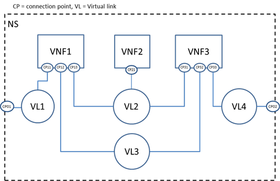
Figure 1.
Example network connectivity topology graph
Each Virtual link (VL) describes the basic topology of the
connectivity as well as other required parameters (e.g. bandwidth and QoS
class). Examples of virtual link types in VNF-NCTs include:
·
E-Line, E-LAN, and E-TREE (defined by the Metro Ethernet Forum in
MEF Technical Specification MEF 6.1: Ethernet Services Definitions - Phase
2", April, 2008).
·
VPLS and VPWS Services (e.g. defined by IETF RFC 4761).
·
Different types of Virtual LANs or Private Virtual LANs (e.g.
IETF RFC 3069).
·
Different types of Layer 2 Virtual Private Networks (e.g. IETF
RFC 4464).
·
Different types of Layer 3 Virtual Private Networks (e.g. IETF
RFC 3809).
·
Different types of Multi-Protocol Label Switching Networks (e.g.
IETF RFC 3031).
·
Other types of layer 2 services, such as Pseudo Wire Switching
for providing multiple Virtual Leased Line Services (e.g. IETF RFC 4385).
The deployment template in NFV fully describes the
attributes and requirements necessary to realize such a Network Service.
Network Service Orchestration coordinates the lifecycle of VNFs that jointly
realize a Network Service. This includes (not limited to) managing the
associations between different VNFs, the topology of the Network Service, and
the VNFFGs associated with the Network Service.
The deployment template for a network service in NFV is
called a network service descriptor (NSD), it describes a relationship between
VNFs and possibly PNFs that it contains and the links needed to connect VNFs.
There are four information elements defined apart from the
top level Network Service (NS) information element:
·
Virtualized Network Function (VNF) information element
·
Physical Network Function (PNF) information element
·
Virtual Link (VL) information element
·
VNF Forwarding Graph (VNFFG) information element
A VNF Descriptor (VNFD) is a deployment template which
describes a VNF in terms of its deployment and operational behavior
requirements.
A VNF Forwarding Graph Descriptor (VNFFGD) is a deployment
template which describes a topology of the Network Service or a portion of the
Network Service, by referencing VNFs and PNFs and Virtual Links that connect
them.
A Virtual Link Descriptor (VLD) is a deployment template
which describes the resource requirements that are needed for a link between
VNFs, PNFs and endpoints of the Network Service, which could be met by various
link options that are available in the NFVI.
A Physical Network Function Descriptor (PNFD) describes the
connectivity, Interface and KPIs requirements of Virtual Links to an attached
Physical Network Function.
The NFVO receives all descriptors and on-boards to the
catalogues, NSD, VNFFGD, and VLD are “on-boarded” into a NS Catalogue; VNFD is
on-boarded in a VNF Catalogue, as part of a VNF Package. At the instantiation
procedure, the sender (operator) sends an instantiation request which contains
instantiation input parameters that are used to customize a specific
instantiation of a network service or VNF. Instantiation input parameters
contain information that identifies a deployment flavor to be used and those
parameters used for the specific instance.
At the top level of TOSCA data model is a service template,
within a service template, it includes several node templates with different
types. In NFV, NSD is at the top level, under NSD, it includes VNFD, VNFFGD,
VLD and PNFD. The mapping between TOSCA and NFV takes the following approach.
- NSD is described by using a service template,
- VNFD, VNFFGD, VLD and PNFD is considered as node templates
with appropriate node types.
- VNFD can be further described by using another service
template with substitutable node type.
The mapping relationship between TOSCA and NFV is showing in
Figure 3.
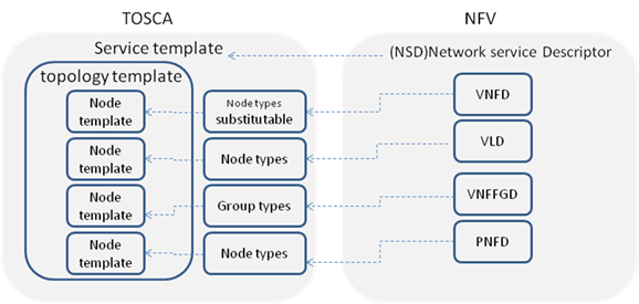
Figure 2.
General mapping between TOSCA and NFV
As described in NFV, NSD describes the attributes and
requirements necessary to realize a Network Service. Figure 2 is a network
service example given by NFV MANO specification [ETSI GS NFV-MAN 001 v1.1.1]. In this
example, the network service includes three VNFs. Each VNF exposes different
number of connection points, which represent the virtual and/or physical
interface of VNFs. Virtual link (VL) describes the basic topology of the
connectivity (e.g. ELAN, ELINE, ETREE) between one or more VNFs connected to
this VL and other required parameters (e.g. bandwidth and QoS class).

Figure 3.
Network service example for NFV
For simplicity, the VNF and its connection point can be considered
as a subsystem of the network service. And a new relationship type is needed to
connect VNF and virtual link. Figure 3 shows how the TOSCA node, capability and
relationship types enable modeling the NFV application using virtualLinkTo
relationship between VNF and virtual link.
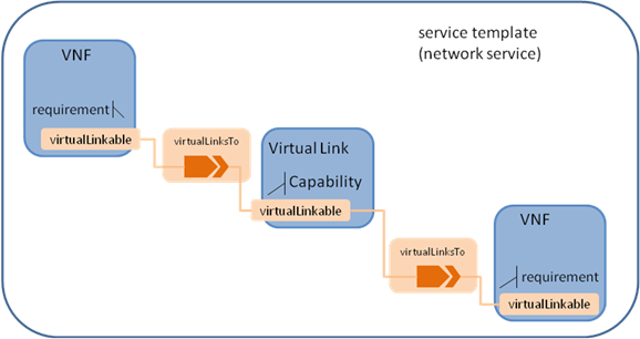
Figure 4.
TOSCA node, capability and relationship types used in NFV application
The virtualLinkable requirement of VNF is exposed by the
connection point of that VNF who act as an endpoint.
The following table defines the namespace alias and (target)
namespace values that SHALL be used when referencing the TOSCA simple Profile for
NFV version 1.0 specification.
A VNF can be considered as a subsystem in a network service,
it can include:
·
VDU, which is a subset of a VNF. A VDU can be mapped to a single
VM;
·
Connection point, some of connection points are only used to connect
internal virtual link, while others are exposed to connect outside virtual
link. A connection point has to bind with a VDU.
·
Internal virtual link, the main functionalities are the same with
the virtual link defined in the network service level, but it is only used
within VNF to provide connectivity between VDUs.
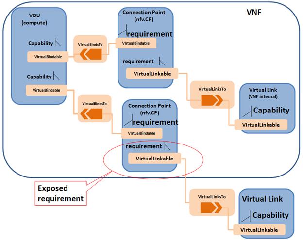
Figure 5.
TOSCA node, capability and relationship types used in VNF application
The substitution mapping feature as defined in [TOSCA-Simple-Profile-YAML],
is used to define a new node type, which its characteristics can be mapped to
internal elements of a service template.
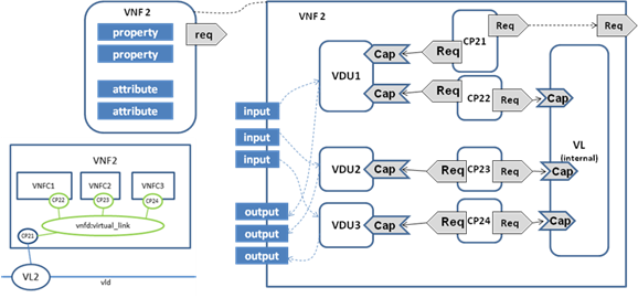
Figure 6.
Substitution mapping for a VNF node type to a service template
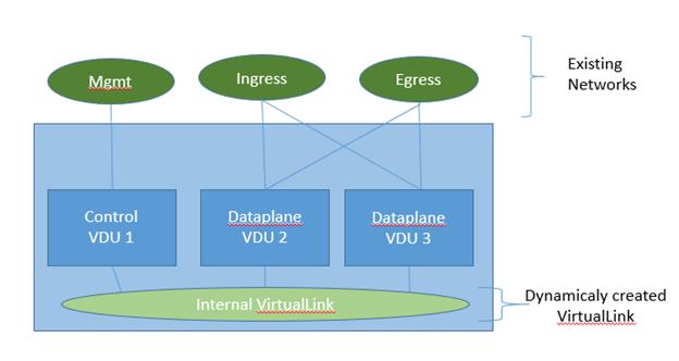
Figure 8 shows an example of the internal structure of a
VNF. In this example, VNF2 comprises 3 VDUs which connect to an internal
Virtual Link. The first VDU has two Connection Points: one (CP21) used to connect
the external Virtual Link, another one used (CP22) to connect the internal
Virtual Link. VDU provides the capability Bindable to bind Connection Point.
Connection point has two requirements, bindable and virtualLinkable. The
connection point that has the requirement to the external virtual link exposes
the virtualLinkable requirement of the VNF. The external connection point also
has Forwarder capability, used to form the network forwarding path. In the
example as shown in Figure 8, CP21 is the external connection point of VNF2.
|
tosca_definitions _version:
tosca_simple_profile_for_nfv_1_0
description: example for VNF2
metadata:
ID:
# ID of this Network Service Descriptor
vendor:
# Provider or vendor of the Network Service
version:
# Version of the Network Service Descriptor
topology_template:
inputs:
subsititution_mappings:
node_type: tosca.nodes.nfv.VNF.VNF2
requirements:
virtualLink1: [CP21,
virtualLink]
capabilities:
forwarder1: [CP21,
Forwarder]
node_templates:
VDU1:
type:
tosca.nodes.nfv.VDU
properties:
# omitted here for brivity
requirements:
-
host:
node_filter:
capabilities:
# Constraints for selecting “host” (Container Capability)
- host
properties:
- num_cpus: { in_range: [ 1, 4 ] }
- mem_size: { greater_or_equal: 2 GB }
-
artifacts:
VM_image:vdu1.image #the VM image of VDU1
Interface:
Standard:
create:vdu1_install.sh
configure:
implementation:
vdu1_configure.sh
VDU2:
type:
tosca.nodes.nfv.VDU
properties:
# omitted here for brivity
VDU3:
type:
tosca.nodes.nfv.VDU
properties:
# omitted here for brivity
CP21: #endpoints
of VNF2
type:
tosca.nodes.nfv.CP
properties:
type:
requirements:
virtualbinding: VDU1
capabilities:
Forwarder
CP22:
type:
tosca.nodes.nfv.CP
properties:
type:
requirements:
virtualbinding: VDU1
virtualLink: internal_VL
CP23
type:
tosca.nodes.nfv.CP
properties:
type:
requirements:
virtualbinding: VDU2
virtualLink: internal_VL
CP24
type:
tosca.nodes.nfv.CP
properties:
type:
requirements:
virtualbinding: VDU3
virtualLink: internal_VL
internal_VL
type:
tosca.nodes.nfv.VL.ELAN
properties:
# omitted here for brivity
capabilities:
-virtual_linkable
occurrences: 5
|
In the example above, ID, vender and version are defined service_properties
for VNFD specific usage. The topology_template defines the internal structure
of VNF2. In the subsititution_mappings element, it defines the node type as
tosca.nodes.nfv.vnf2 which is the substitutable node type as defined by this
service template. The virtualLinkable requirement is exposed by the
virtualLinkable requirement of CP21.
VDU as a compute component in VNF, has requirement for
compute and memory, it may also include VM image, which can be described as
artifact. CP21 as the endpoint of VNF2, has binding requirement for VDU1, and
virtualLinkable requirement for external virtual link. CP22, CP23 and CP24 are
internal connection point of VNF2, which all connect to the internal_VL.
Enhance compute architecture capability that needs to be
typically use for performance sensitive NFV workloads.
|
Shorthand Name
|
Compute.Container.Architecture
|
|
Type Qualified Name
|
tosca:Compute.Contrainer.Architecture
|
|
Type URI
|
tosca.capabilities.Compute.Container.Architecture
|
8.2.1.1 Properties
|
Name
|
Required
|
Type
|
Constraints
|
Description
|
|
mem_page_size
|
No
|
string
|
One of:
·
small
·
large
·
any
·
custom mem in MB
Default: any
|
Describe page size of the VM
small page size is typically 4KB
large page size is typically 2MB
any page size maps to system default
custom MB value: sets TLB size to this specific value
|
|
cpu_allocation
|
no
|
CPUAllocation
|
|
Describes CPU allocation requirements like dedicated CPUs
(cpu pinning), socket count, thread count, etc.
|
|
numa_node_count
|
no
|
Integer
|
|
Specifies the symmetric count of NUMA nodes to expose to
the VM. vCPU and Memory equally split across this number of NUMA.
NOTE: the map of numa_nodes should not be specified.
|
|
numa_nodes
|
no
|
map of NUMA
|
|
Asymmetric allocation of vCPU and Memory across the
specific NUMA nodes (CPU sockets and memory banks).
NOTE: symmetric numa_node_count should not be specified
|
8.2.1.2 Definition
|
tosca.capabilities.Compute.Container.Architecture:
derived_from: tosca.capabilities.Container
properties:
mem_page_size:
type: scalar-unit.size
required: false
constraints:
- [normal, huge]
cpu_allocation:
type: tosca.datatypes.compute.Container.Architecture.CPUAllocation
required: false
numa_nodes:
type: map
entry_schema:
tosca.datatypes.compute.Container.Architecture.NUMA
|
A node type that includes the VirtualBindable capability
indicates that it can be pointed by tosca.relationships.nfv.VirtualBindsTo
relationship type.
|
Shorthand Name
|
VirtualBindable
|
|
Type Qualified Name
|
tosca: VirtualBindable
|
|
Type URI
|
tosca.capabilities.nfv.VirtualBindable
|
|
Name
|
Required
|
Type
|
Constraints
|
Description
|
|
N/A
|
N/A
|
N/A
|
N/A
|
N/A
|
|
tosca.capabilities.nfv.VirtualBindable:
derived_from: tosca.capabilities.Node
|
A node type that includes the Metric capability indicates
that it can be monitored using an nfv.relationships.Monitor relationship type.
|
Shorthand Name
|
Metric
|
|
Type Qualified Name
|
tosca:Metric
|
|
Type URI
|
tosca.capabilities.nfv.Metric
|
|
Name
|
Required
|
Type
|
Constraints
|
Description
|
|
N/A
|
N/A
|
N/A
|
N/A
|
N/A
|
|
tosca.capabilities.nfv.Metric:
derived_from: tosca.capabilities.Endpoint
|
Granular CPU allocation requirements for NFV
workloads.
|
Shorthand Name
|
CPUAllocation
|
|
Type Qualified Name
|
tosca:CPUAllocation
|
|
Type URI
|
tosca.datatypes.compute.Container.Architecture.CPUAllocation
|
8.3.1.1 Properties
|
Name
|
Type
|
Constraints
|
Description
|
|
cpu_affinity
|
String
|
One of:
·
shared
·
dedicated
|
Describes whether vCPU need to be pinned to dedicated CPU
core or shared dynamically
|
|
thread_allocation
|
String
|
One of:
·
avoid
·
separate
·
isolate
·
prefer
|
Describe thread allocation requirement
|
|
socket_count
|
Integer
|
None
|
Number of CPU sockets
|
|
core_count
|
Integer
|
None
|
Number of cores per socket
|
|
thread_count
|
Integer
|
None
|
Number of threads per core
|
8.3.1.2 Definition
TBD
8.3.1.3 Examples
TBD
Granular Non-Uniform Memory Access (NUMA) topology
requirements for NFV workloads
|
Shorthand Name
|
NUMA
|
|
Type Qualified Name
|
tosca:NUMA
|
|
Type URI
|
tosca.datatypes.compute.Container.Architecture.NUMA
|
8.3.2.1 Properties
|
Name
|
Type
|
Constraints
|
Description
|
|
id
|
integer
|
greater_or_eq: 0
|
CPU socket identifier
|
|
vcpus
|
map of integers
|
none
|
List of specific host cpu numbers within a NUMA socket
complex
TODO: need a new base type, with non-overlapping, positive
value validation (exclusivity)
|
|
mem_size
|
scalar-unit.size
|
greater_or_equal: 0MB
|
Size of memory allocated from this NUMA memory bank
|
8.3.2.2 Definition
TBD
8.3.2.3 Examples
TBD
This relationship type represents an association
relationship between VDU and CP node types.
|
Shorthand Name
|
VirtualBindsTo
|
|
Type Qualified Name
|
tosca: VirtualBindsTo
|
|
Type URI
|
tosca.relationships.nfv. VirtualBindsTo
|
|
tosca.relationships.nfv.VirtualBindsTo:
derived_from: tosca.relationships.DependsOn
valid_target_types: [ tosca.capabilities.nfv.VirtualBindable]
|
This relationship type represents an association
relationship to the Metric capability of VDU node types.
|
Shorthand Name
|
Monitor
|
|
Type Qualified Name
|
tosca:Monitor
|
|
Type URI
|
tosca.relationships.nfv.Monitor
|
|
tosca.relationships.nfv.Monitor:
derived_from: tosca.relationships.ConnectsTo
valid_target_types: [ tosca.capabilities.nfv.Metric]
|
The NFV VNF Node Type represents a Virtual Network Function as
defined by [ETSI GS NFV-MAN 001 v1.1.1]. It is the default type that all
other VNF Node Types derive from. This allows for all VNF nodes to have a
consistent set of features for modeling and management (e.g., consistent
definitions for requirements, capabilities and lifecycle interfaces).
|
tosca.nodes.nfv.VNF:
derived_from: tosca.nodes.Root
# Or should this be its own top-level type?
properties:
id:
type:
string
description: ID of this VNF
vendor:
type:
string
description: name of the vendor who generate this VNF
version:
type:
version
description: version of the software for this VNF
requirements:
- virtualLink:
capability:
tosca.capabilities.nfv.VirtualLinkable
relationship: tosca.relationships.nfv.VirtualLinksTo
|
The NFV vdu node type represents a logical vdu entity as
defined by [ETSI GS NFV-MAN 001 v1.1.1].
|
Shorthand Name
|
VDU
|
|
Type Qualified Name
|
tosca:VDU
|
|
Type URI
|
tosca.nodes.nfv.VDU
|
|
Name
|
Type
|
Constraints
|
Description
|
|
monitoring_parameter
|
nvf.Metric
|
None
|
Monitoring parameter, which can be tracked for
a VNFC based on this VDU
Examples include: memory-consumption, CPU-utilisation,
bandwidth-consumption, VNFC downtime, etc.
|
|
|
|
|
|
|
virtualbinding
|
tosca.Bindable
|
|
Defines ability of VirtualBindable
|
|
tosca.nodes.nfv.VDU:
derived_from: tosca.nodes.Root
capabilities:
nfv_compute:
type:
tosca.capabilities.Compute.Container.Architecture
virtualbinding:
type:
tosca.capabilities.nfv.VirtualBindable
monitoring_parameter:
type:
tosca.capabilities.nfv.Metric requirements:
-
|
8.5.2.3 VDU Artifact
The NFV profile maps VDU to a Virtual Machine. When creating
a VDU node, apart from creating a VM with properties specified in nfv_compute,
a VM image is needed. To specify the image the recommended way is to use
artifact type. Here is an example,
node_templates:
VDU1:
type: tosca.nodes.nfv.VDU
capabilities:
…
artifacts:
VDU1Image:
type: tosca.artifacts.Deployment.Image.VM
The NFV CP node represents a logical connection point entity
as defined by [ETSI GS NFV-MAN 001 v1.1.1]. A
connection point may be, for example, a virtual port, a virtual NIC address, a
physical port, a physical NIC address or the endpoint of an IP VPN enabling
network connectivity. It is assumed that each type of connection point will be
modeled using subtypes of the CP type.
|
Shorthand Name
|
CP
|
|
Type Qualified Name
|
tosca:CP
|
|
Type URI
|
tosca.nodes.nfv.CP
|
|
Name
|
Required
|
Type
|
Constraints
|
Description
|
|
type
|
yes
|
string
|
None
|
This may be, for example, a virtual port, a virtual NIC
address, a SR-IOV port, a physical port, a physical NIC address or the
endpoint of an IP VPN enabling network connectivity.
|
|
anti_spoof_protection
|
no
|
boolean
|
None
|
Indicates of whether anti-spoofing rule need to be enabled
for this vNIC. This is applicable only when CP type is virtual NIC (vPort)
|
|
Name
|
Required
|
Type
|
Constraints
|
Description
|
|
address
|
no
|
string
|
None
|
The actual virtual NIC address that is been assigned when
instantiating the connection point
|
|
tosca.nodes.nfv.CP:
derived_from: tosca.nodes.network.Port
properties:
type:
type: string
required:
false
anti_spoof_protection:
type:
boolean
required: false
requirements:
- virtualLink:
capability:
tosca.capabilities.nfv.VirtualLinkable
relationship: tosca.relationships.nfv.VirtualLinksTo
- virtualbinding:
capability:
tosca.capabilities.nfv.VirtualBindable
relationship: tosca.relationships.nfv.VirtualBindsTo
attributes:
address:
type: string
|
The NFV VL node type represents a logical virtual link
entity as defined by [ETSI GS NFV-MAN 001 v1.1.1]. It
is the default type from which all other virtual link types derive.
|
Shorthand Name
|
VL
|
|
Type Qualified Name
|
tosca:VL
|
|
Type URI
|
tosca.nodes.nfv.VL
|
|
Name
|
Required
|
Type
|
Constraints
|
Description
|
|
vendor
|
yes
|
string
|
None
|
Vendor generating this VLD
|
|
tosca.nodes.nfv.VL:
derived_from: tosca.nodes.network.Network
properties:
vendor:
type:
string
required:
true
description:
name of the vendor who generate this VL
capabilities:
virtual_linkable:
type: tosca.capabilities.nfv.VirtualLinkable
|
The NFV VL.ELine node represents an E-Line virtual link
entity.
|
tosca.nodes.nfv.VL.ELine:
derived_from: tosca.nodes.nfv.VL
capabilities:
virtual_linkable:
occurrences: 2
|
The NFV VL.ELan node represents an E-LAN virtual link entity.
|
tosca.nodes.nfv.VL.ELAN:
derived_from: tosca.nodes.network.Network
|
The NFV VL.ETree node represents an E-Tree virtual link
entity.
|
tosca.nodes.nfv.VL.ETree:
derived_from: tosca.nodes.nfv.VL
|
A VNF forwarding graph is specified by a Network Service
Provider to define how traffic matching certain criteria is intended to flow
through one or more network functions in a Network Connectivity Topology in
order to accomplish the desired network service functionality. The NFV
specification describes network forwarding graphs using one or more Network
Forwarding Paths. A Network Forwarding Path is an ordered lists of
Connection Points that form a chain of VNFs. The order of network functions
applied is application-dependent, and may be a simple sequential set of
functions, or a more complex graph with alternative paths (e.g. the service may
fork, and even later combine), depending on the nature of the traffic, the
context of the network, and other factors.
The following figure shows an example of two VNF Forwarding
Graphs established on top of the Network Connectivity Topology described
earlier. VNFFG1 has two Network Forwarding Paths (VNFFG1:NFP1 and VNFFG1:NFP2)
whereas VNFFG2 only has a single NFP (VNFFG2:NFP1).
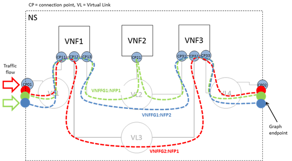
Figure 7.
Multiple forwarding graphs using the same network connectivity graph
As described by [ETSI GS NFV-MAN 001
v1.1.1], VNFFG is a
deployment template which describes a topology of the network service or a
portion of the network service. When TOSCA metamodel is used, the
group concept as defined in TOSCA shall be used to described the VNFFGD,
·
the referenced VNFs, PNFs, virtual links and connection points
shall be defined as the properties in the VNFFG group, and
·
the network forwarding paths element shall be defined as
the targets in the VNFFG group
Network forwarding path as defined by [ETSI
GS NFV-MAN 001 v1.1.1]
is an order list of connection points forming a chain of network functions
(VNFs or PNFs). A new “Forwarder” requirement is defined in this
specification to model the network forwarding path by using ordered
list of multiple “Forwarder” requirements. Each “Forwarder” requirement
points to a single connection point. The following diagram gives an example to
show how to use “Forwarder” requirements to describe a forwarding path. 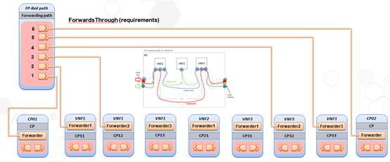
A node type that includes the Forwarder capability indicates
that it can be pointed by tosca.relationships.nfv.FowardsTo relationship type.
|
Shorthand Name
|
Forwarder
|
|
Type Qualified Name
|
tosca: Forwarder
|
|
Type URI
|
tosca.capabilities.nfv.Forwarder
|
10.3.1.1 Properties
|
Name
|
Required
|
Type
|
Constraints
|
Description
|
|
N/A
|
N/A
|
N/A
|
N/A
|
N/A
|
10.3.1.2 Definition
|
tosca.capabilities.nfv.Forwarder:
derived_from: tosca.capabilities.Root
|
This relationship type represents a traffic flow between two
connection point node types.
|
Shorthand Name
|
ForwardsTo
|
|
Type Qualified Name
|
tosca: ForwardsTo
|
|
Type URI
|
tosca.relationships.nfv. ForwardsTo
|
10.4.1.1 Definition
|
tosca.relationships.nfv.ForwardsTo:
derived_from: tosca.relationships.Root
valid_target_types: [ tosca.capabilities.nfv.Forwarder]
|
The NFV FP node type represents a logical network forwarding
path entity as defined by [ETSI GS NFV-MAN 001 v1.1.1].
|
Shorthand Name
|
VL
|
|
Type Qualified Name
|
tosca:FP
|
|
Type URI
|
tosca.nodes.nfv.FP
|
|
Name
|
Required
|
Type
|
Constraints
|
Description
|
|
policy
|
no
|
string
|
None
|
A policy or rule to apply to the NFP
|
|
tosca.nodes.nfv.FP:
derived_from: tosca.nodes.Root
properties:
policy:
type:
string
required:
false
description:
name of the vendor who generate this VL
requirements:
- forwarder:
capability: tosca.capabilities.nfv.Forwarder
|
The NFV VNFFG group type represents a logical VNF forwarding
graph entity as defined by [ETSI GS NFV-MAN 001 v1.1.1].
|
Shorthand Name
|
VL
|
|
Type Qualified Name
|
tosca:VNFFG
|
|
Type URI
|
tosca.groups.nfv.VNFFG
|
|
Name
|
Required
|
Type
|
Constraints
|
Description
|
|
vendor
|
yes
|
string
|
None
|
Specify the vendor generating this VNFFG.
|
|
Version
|
yes
|
version
|
None
|
Specify the identifier (e.g. name), version, and
description of service this VNFFG is describing.
|
|
number_of_endpoints
|
yes
|
integer
|
None
|
Count of the external endpoints included
in this VNFFG, to form an index
|
|
dependent_virtual_
link
|
yes
|
string[]
|
None
|
Reference to a list of VLD used in this Forwarding Graph
|
|
connection_point
|
yes
|
string[]
|
|
Reference to Connection Points forming the VNFFG
|
|
constituent_vnfs
|
yes
|
string[]
|
|
Reference to a list of VNFD used in this VNF Forwarding
Graph
|
|
tosca.groups.nfv.VNFFG:
derived_from: tosca.groups.Root
properties:
vendor:
type:
string
required:
true
description:
name of the vendor who generate this VNFFG
version:
type:
string
required:
true
description:
version of this
VNFFG
number_of_endpoints:
type:
integer
required:
true
description:
count of the external endpoints included in this
VNFFG
dependent_virtual_link:
type:
list
entry_schema:
type: string
required:
true
description:
Reference to a
VLD used in this Forwarding Graph
connection_point:
type:
list
entry_schema: string
required:
true
description:
Reference to Connection Points
forming the VNFFG
constituent_vnfs:
type:
list
entry_schema:
type: string
required:
true
description:
Reference to a list of VNFD used in this
VNF Forwarding Graph
targets: [
tosca.nodes.nfv.FP ]
|
The following is the list of recognized metadata
keynames for a TOSCA Service Template for NFV definition:
|
Keyname
|
Required
|
Type
|
Description
|
|
ID
|
yes
|
string
|
ID of this Network Service
Descriptor
|
|
vendor
|
yes
|
string
|
Provider or vendor of the
Network Service
|
|
version
|
yes
|
string
|
Version of the Network Service Descriptor
|
The use case of a network service is shown in Figure 6. This
section uses a TOSCA service template to describe the network service as shown
in Figure 4.
|
tosca_definitions_version: tosca_simple_profile_for_nfv_1_0
tosca_default_namespace: # Optional. default
namespace (schema, types version)
description: example for a NSD.
metadata:
ID:
# ID of this Network Service Descriptor
vendor:
# Provider or vendor of the Network Service
version:
# Version of the Network Service Descriptor
imports:
- tosca_base_type_definition.yaml
# list of import statements for importing
other definitions files
topology_template:
inputs:
flavor ID:
VNF1:
type: tosca.nodes.nfv.VNF.VNF1
properties:
Scaling_methodology:
Flavour_ID:
Threshold:
Auto-scale policy value:
Constraints:
requirements:
virtualLink1: VL1
# the subsititution mappings in VNF1 has virtualLink1:
[CP11, virtualLink]
virtualLink2: VL2
# the subsititution mappings in VNF1 has virtualLink2:
[CP12, virtualLink]
virtualLink3: VL3
# the subsititution mappings in VNF1 has virtualLink3:
[CP13, virtualLink]
capabilities:
forwarder1 #
the subsititution mappings in VNF1 has forwarder1:
[CP11, forwarder]
forwarder2
# the subsititution mappings in VNF1 has forwarder2:
[CP12, forwarder]
forwarder3
# the subsititution mappings in VNF1 has forwarder3:
[CP13, forwarder]
VNF2:
type:
tosca.nodes.nfv.VNF.VNF2
properties:
Scaling_methodology:
Flavour_ID:
Threshold:
Auto-scale policy value:
Constraints:
requirements:
virtualLink1: VL2 # the subsititution mappings in VNF2 has virtualLink1:
[CP21, virtualLink]
capabilities:
forwarder1 # the
subsititution mappings in VNF1 has forwarder1:
[CP21, forwarder]
VNF3:
type:
tosca.nodes.nfv.VNF.VNF3
properties:
Scaling_methodology:
Flavour_ID:
Threshold:
Auto-scale policy value:
Constraints:
requirements:
virtualLink1: VL2 # the subsititution mappings in VNF3 has virtualLink1:
[CP31, virtualLink]
virtualLink2: VL3 # the
subsititution mappings in VNF3 has virtualLink2:
[CP32, virtualLink]
virtualLink3: VL4 # the
subsititution mappings in VNF3 has virtualLink3:
[CP33, virtualLink]
capabilities:
forwarder1 # the
subsititution mappings in VNF1 has forwarder1:
[CP31, forwarder]
forwarder2 # the
subsititution mappings in VNF1 has forwarder2:
[CP32, forwarder]
forwarder3
# the subsititution mappings in VNF1 has forwarder3:
[CP33, forwarder]
CP01
#endpoints of NS
type: tosca.nodes.nfv.CP
properties:
type:
requirements:
virtualLink: VL1
CP02
#endpoints of NS
type: tosca.nodes.nfv.CP
properties:
type:
requirements:
virtualLink: VL4
VL1
type: tosca.nodes.nfv.VL.Eline
properties:
# omitted
here for brevity
capabilities:
-virtual_linkable
occurrences: 2
VL2
type: tosca.nodes.nfv.VL.ELAN
properties:
# omitted here for brevity
capabilities:
-virtual_linkable
occurrences: 5
VL3
type: tosca.nodes.nfv.VL.Eline
properties:
# omitted here for brevity
capabilities:
-virtual_linkable
occurrences: 2
VL4
type: tosca.nodes.nfv.VL.Eline
properties:
# omitted here for brevity
capabilities:
-virtual_linkable
occurrences: 2
Forwarding path1:
type:
tosca.nodes.nfv.FP
description: the path (CP01àCP11àCP13àCP21àCP31àCP33àCP02)
properties:
policy:
requirements:
-forwarder:
CP01
-forwarder:
VNF1
capability: forwarder1 #CP11
-forwarder:
VNF1
capability:
forwarder3 #CP13
-forwarder: VNF2
capability:
forwarder1 #CP21
-forwarder:
VNF3
capability: forwarder1 #CP31
-forwarder:
VNF3
capability: forwarder3 #CP33
-forwarder:
CP02
Forwarding path2:
type:
tosca.nodes.nfv.FP
description: the path (CP01àCP11àCP13àCP31àCP33àCP02)
properties:
policy:
requirements:
-forwarder:
CP01
-forwarder:
VNF1
capability: forwarder1 #CP11
-forwarder:
VNF1
capability: forwarder3 #CP13
-forwarder:
VNF3
capability: forwarder1 #CP31
-forwarder:
VNF3
capability: forwarder3 #CP33
-forwarder:
CP02
Forwarding path3:
type:
tosca.nodes.nfv.FP
description: the path (CP01àCP11àCP12àCP32àCP33àCP02)
properties:
policy:
requirements:
-forwarder:
CP01
-forwarder:
VNF1
capability: forwarder1
#CP11
-forwarder:
VNF1
capability:
forwarder2 #CP12
-forwarder:
VNF3
capability: forwarder2 #CP32
-forwarder:
VNF3
capability: forwarder3 #CP33
-forwarder:
CP02
Groups:
VNFFG1:
type: tosca.groups.nfv.vnffg
description: forwarding graph
1
properties:
vendor:
version:
vl: [VL1,VL2,VL4]
vnf: [VNF1,VNF2,VNF3]
targets: [Forwarding path1, Forwarding path2]
VNFFG2:
type: tosca.groups.nfv.vnffg
description: forwarding graph
2
properties:
vendor:
version:
vl: [VL1,VL3,VL4]
vnf: [VNF1,VNF2]
targets: [Forwarding path3]
|
In the example above, metadata element is used to define the
service specific properties, as used in NFV, those NFV specific properties are
ID, vender, version. Each VNF is described as a node template, which type is substituted
by a different service template. As defined in VNF1, it has three requirements,
each for a different virtual link, VL1, VL2 and VL3. VNF2 only has
virtualLinkable requirement to VL2. VNF3 has three virtualLinkable requirements
to VL2, VL3, VL4 respectively. CP01 and CP02 are acting as the endpoints of the
network service. CP01 has virtualLinkable requirement to VL1, and CP02 has
virtualLinkable requirement to VL4. VL1, VL2, VL3 and VL4 are described as node
templates with tosca.nodes.nfv.virtualLink node type.
A node type that includes the VirtualLinkable capability
indicates that it can be pointed by tosca.relationships.nfv.VirtualLinksTo
relationship type.
|
Shorthand Name
|
VirtualLinkable
|
|
Type Qualified Name
|
tosca:VirtualLinkable
|
|
Type URI
|
tosca.capabilities.nfv.VirtualLinkable
|
11.3.1.1 Properties
|
Name
|
Required
|
Type
|
Constraints
|
Description
|
|
N/A
|
N/A
|
N/A
|
N/A
|
N/A
|
11.3.1.2 Definition
|
tosca.capabilities.nfv.VirtualLinkable:
derived_from: tosca.capabilities.Node
|
This relationship type represents an association
relationship between VNFs and VL node types.
|
Shorthand Name
|
VirtualLinksTo
|
|
Type Qualified Name
|
tosca:VirtualLinksTo
|
|
Type URI
|
tosca.relationships.nfv.VirtualLinksTo
|
11.4.1.1 Definition
|
tosca_definitions_version:
tosca_simple_profile_for_nfv_1_0
description:
Simple Virtual Router with one VDU
metadata:
ID:
vRouter-1-0-0
vendor: Acme
version: 1.0
node_types:
vRouterVNF:
derived_from: tosca.nodes.nfv.VNF
capabilities:
forwarder_ingres:
type: tosca.capabilities.nfv.Forwarder
forwarder_egres:
type: tosca.capabilities.nfv.Forwarder
topology_template:
#
inputs:
substitution_mappings:
node_type: vRouterVNF
requirements:
virtualLink: [CP12, virtualLink]
virtualLink: [CP13, virtualLink]
capabilities:
forwarder_ingres: [CP12, forwarder]
forwarder_egres: [CP13, forwarder]
node_templates:
VDU1:
type: tosca.nodes.nfv.VDU
capabilities:
nfv_compute:
properties:
num_cpus: 4
mem_size: 4096 MB
disk_size: 8 GB
artifacts:
vRouterImage:
type: tosca.artifacts.Deployment.Image.VM
file: vdu1.image #the VM image of VDU1
interfaces:
Standard:
configure:
implementation: vdu1_configure.sh
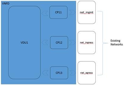
CP11:
type: tosca.nodes.nfv.CP
requirements:
- virtualbinding: VDU1
- virtualLink: net_mgmt
CP12:
type: tosca.nodes.nfv.CP
properties:
anti_spoof_protection: false
requirements:
- virtualbinding: VDU1
- virtualLink: net_ingress
CP13:
type: tosca.nodes.nfv.CP
properties:
anti_spoof_protection: false
requirements:
- virtualbinding: VDU1
- virtualLink: net_egress
net_mgmt:
type: tosca.nodes.nfv.VL.ELAN
net_ingress:
type: tosca.nodes.nfv.VL.ELAN
net_egress:
type: tosca.nodes.nfv.VL.ELAN
|
|
tosca_definitions_version:
tosca_simple_for_nfv_1_0
description:
Sample Virtual Router with one VDU with efficient CPU and Memory properties
metadata:
ID:
vRouter-1-0-0
vendor: Acme
version: 1.0
node_types:
vRouterVNF:
derived_from: tosca.nodes.nfv.VNF
capabilities:
forwarder_ingres:
type: tosca.capabilities.nfv.Forwarder
forwarder_egres:
type: tosca.capabilities.nfv.Forwarder
topology_template:
#
inputs:
substitution_mappings:
node_type: vRouterVNF
requirements:
virtualLink: [CP12, virtualLink]
virtualLink: [CP13, virtualLink]
capabilities:
forwarder_ingres: [CP12, forwarder]
forwarder_egres: [CP13, forwarder]
node_templates:
VDU1:
type: tosca.nodes.nfv.VDU
capabilities:
nfv_compute:
properties:
num_cpus: 8
mem_size: 4096 MB
disk_size: 8 GB
mem_page_size: large
cpu_allocation:
cpu_affinity: dedicated
thread_allocation: isolate
socket_count: 2
core_count: 2
thread_count: 4
numa_nodes:
node0: [ id: 0, vcpus: [ 2, 3 ], mem_size: 2 GB]
node1: [ id: 1, vcpus: [ 4, 5, 6, 7, 8, 9], mem_size: 6 GB]
artifacts:
VM_image:
type: tosca.artifacts.Deployment.Image.VM
file: vdu1.image #the VM image of VDU1
interfaces:
Standard:
create: vdu1_install.sh
configure:
implementation: vdu1_configure.sh
CP11:
type: tosca.nodes.nfv.CP
requirements:
- virtualbinding: VDU1
- virtualLink: net_mgmt
CP12:
type: tosca.nodes.nfv.CP
properties:
anti_spoof_protection: false
requirements:
- virtualbinding: VDU1
- virtualLink: net_ingress
CP13:
type: tosca.nodes.nfv.CP
properties:
anti_spoof_protection: false
requirements:
- virtualbinding: VDU1
- virtualLink: net_egress
net_mgmt:
type: tosca.nodes.nfv.VL.ELAN
net_ingress:
type: tosca.nodes.nfv.VL.ELAN
net_egress:
type: tosca.nodes.nfv.VL.ELAN
|
|
tosca_definitions_version:
tosca_simple_profile_for_nfv_1_0
description:
Sample Virtual Router with multiple VDUs and internal VirtualLink
metadata:
ID:
vRouter-1-0-0
vendor: Acme
version: 1.0
node_types:
vRouterVNF:
derived_from: tosca.nodes.nfv.VNF
capabilities:
forwarder_ingres:
type: tosca.capabilities.nfv.Forwarder
forwarder_egres:
type: tosca.capabilities.nfv.Forwarder
topology_template:
substitution_mappings:
node_type: vRouterVNF
requirements:
virtualLink: [CP12, virtualLink]
virtualLink: [CP13, virtualLink]
capabilities:
forwarder_ingres: [CP12, forwarder]
forwarder_egres: [CP13, forwarder]
topology_template:
node_templates:
VDU1:
type: tosca.nodes.nfv.VDU
capabilities:
nfv_compute:
properties:
num_cpus: 2
mem_size: 2048 MB
disk_size: 8 GB
artifacts:
vRouterVNFImage:
type: tosca.artifacts.Deployment.Image.VM.QCOW2
file: http://filer/vnf/vRouterVNF_ControlPlane.qcow2
VDU2:
type: tosca.nodes.nfv.VDU
capabilities:
nfv_compute:
properties:
num_cpus: 6
mem_size: 4096
disk_size: 8
artifacts:
vRouterVNFImage:
type: tosca.artifacts.Deployment.Image.VM.QCOW2
file: http://filer/vnf/vRouterVNF_DataPlane.qcow2
VDU3:
type: tosca.nodes.nfv.VDU
capabilities:
nfv_compute:
properties:
num_cpus: 6
mem_size: 4096
disk_size: 8
artifacts:
vRouterVNFImage:
type: tosca.artifacts.Deployment.Image.VM.QCOW2
file: http://filer/vnf/vRouterVNF_DataPlane.qcow2
CP11:
type: tosca.nodes.nfv.CP
properties:
type: vPort
requirements:
- virtualLink: ManagementNetwork
- virtualBinding: VDU1
CP12:
type: tosca.nodes.nfv.CP
properties:
type: vPort
anti_spoofing_protection: false
requirements:
- virtualLink: InternalNetwork
- virtualBinding: VDU1
CP21:
type: tosca.nodes.nfv.CP
properties:
type: vPort
anti_spoofing_protection: false
requirements:
- virtualLink: InternalNetwork
- virtualBinding: VDU2
CP22:
type: tosca.nodes.nfv.CP
properties:
type: vPort
anti_spoofing_protection: false
requirements:
- virtualLink: IngressNetwork
- virtualBinding: VDU2
CP23:
type: tosca.nodes.nfv.CP
properties:
type: vPort
anti_spoofing_protection: false
requirements:
- virtualLink: EgressNetwork
- virtualBinding: VDU2
CP31:
type: tosca.nodes.nfv.CP
properties:
type: vPort
anti_spoofing_protection: false
requirements:
- virtualLink: InternalNetwork
- virtualBinding: VDU3
CP32:
type: tosca.nodes.nfv.CP
properties:
type: vPort
anti_spoofing_protection: false
requirements:
- virtualLink: IngressNetwork
- virtualBinding: VDU3
CP33:
type: tosca.nodes.nfv.CP
properties:
type: vPort
anti_spoofing_protection: false
requirements:
- virtualLink: EgressNetwork
- virtualBinding: VDU3
InternalNetwork:
type: tosca.nodes.nfv.VL.ELAN
properties:
# Hint to create new virtual network
vendor: ACME Networks
cidr: 10.1.10.0/24
gateway_ip: 10.1.10.1
network_type: vlan
physical_network: phynet1
segmentation_id: 1000
DataplaneNetwork:
type: tosca.nodes.nfv.VL.ELAN
properties:
# Existing dataplane network
name: neutron_net_dp0
ManagementNetwork:
type: tosca.nodes.nfv.VL.ELAN
properties:
# Existing virtual network
name: neutron_net_mgmt
IngressNetwork:
type: tosca.nodes.nfv.VL.ELAN
properties:
# Existing virtual network
name: neutron_net_ingress
EgressNetwork:
type: tosca.nodes.nfv.VL.ELAN
properties:
# Existing virtual network
name: neutron_net_egress
|
The following individuals have participated in the creation
of this specification and are gratefully acknowledged:
Participants:
Chris Lauwers (lauwers@ubicity.com), Ubicity
Derek Palma (dpalma@vnomic.com), Vnomic
Matt Rutkowski (mrutkows@us.ibm.com), IBM
Shitao li (lishitao@huawei.com), Huawei
Lawrence Lamers (ljlamers@vmware.com),
VMware
Sridhar Ramaswamy (sramasw@Brocade.com), Brocade
|
Revision
|
Date
|
Editor
|
Changes Made
|
|
WD01, Rev01
|
2015-2-26
|
Shitao li, Huawei
|
l
Adding clause 1, the introduction
about this profile
l
Adding clause 2, summary of key
TOSCA concepts
l
Adding clause 3, deployment
template in NFV
l
Adding clause 4, general mapping
between TOSCA and NFV deployment template
l
Adding clause 5, describes the
main idea about using a service template for NFV NSD
|
|
WD01, Rev02
|
2015-4-15
|
Shitao li, Huawei
|
l
Changing the NSD example used in clause
5
l
Changing the TOSCA model for NSD
in figure 3 in clause 5, consider a VNF and its connection point as a subsystem
of a NS
l
Adding the TOSCA template example
for NSD in clause 5.1
l
Adding NFV specific service
properties for NSD in clause 5.2, the main properties are id ,vender and
version
l
Adding new capability tosca.capabilities.nfv.VirtualLinkable
in clause 5.3
l
Adding new relationship type tosca.relationships.nfv.VirtualLinkTo
in clause 5.4, which used between connection point and virtual link node
types.
l
Adding clause 6, TOSCA data model for VNFD
l
Adding clause 6.1, node template substitution mapping for a VNF
l
Adding NFV specific service
properties for VNFD in clause 6.2, the main properties are id ,vender and
version
l
Adding new node type tosca.nodes.nfv.vdu in clause 6.3
l
Adding new node type tosca.nodes.nfv.CP in clause 6.4
l
Adding clause 7, TOSCA template for VLD (virtual link
descriptor)
l
Adding new node type tosca.nodes.nfv.VL in clause 7.1
|
|
WD01, Rev03
|
2015-5-5
|
Shitao li, Huawei
Chris Lauwers
|
l
Adding clause 3 for NFV overview
l
Adding namespace for tosca-nfv- profile
in clause 5.1
l
Deleting the NFV specific service
properties for NSD and VNFD
l
Adding capability type
definitions for VNF in clause 7.2(VirtualBindable, HA, HA.ActiveActive,
HA.ActivePassive, Metric)
l
Adding relationship type
definitions for VNF in clause 7.3(VirtualBindsTo, nfv.HA, nfv.Monitor)
l
Adding default VNF node type
definition in clause 7.4.1
l
Changing the VDU node type
definition in clause 7.4.2(treat HA and monitor parameters as capabilities)
l
Adding new node types definition
for VL.Eline, VL.ELAN and VL.ETree in clause 8.2, 8.3 and 8.4.
|
|
WD01, Rev04
|
2015-5-13
|
Chris Lauwers
|
l
Formatting changes
|
|
WD02,Rev01
|
2015-7-2
|
Shitao li, Huawei
|
l
6.1, changing the version number
from 1.0.0 to 1.0
l
6.2, adding NFV usage specific metadata
keynames
l
6.3, using metadata element
instead of service_properties
l
7.1, using metadata element
instead of service_properties
|
|
WD02,Rev02
|
2015-8-26
|
Shitao li, Huawei
|
l
6: change title to “TOSCA Data
model for a network service”, and move the NSD example as well as NSD related
definition to clause 11.
l
7: change title to “TOSCA Data
model for a VNF”
l
8.1: in the text and the VNFD
example, adding Forwarder capability to exteral connection point for
supporting NFP description
l
10: moving VNFFG description text
from clause 3.3 to clause 10.
l
10.1,10.2,10.3,10.4,10.5,10.6:
adding TOSCA model for VNFFG, using group type for VNFFG and node type for
NFP
l
11: moving TOSCA template for NSD
from clause 7 to clause 11.
l
11.2: adding VNFFG and NFP in the
NSD example
|
|
WD02, Rew03
|
2015-9-28
|
Matt Rutkowski, IBM
|
l
11.2: changing NSD example for
NFP, adding “-” in front of every requirement.
|
|
WD02, Rew04
|
2015-10-15
|
Chris Lauwers
|
l
Formatting changes
|
|
WD02, Rew05
|
2016-1-22
|
Sridhar Ramaswamy, Brocade
Shitao li, Huawei
|
l
12, adding new VNFD example for
the single vRouter use case.
|
|
WD02, Rev07
|
2016-2-18
|
Sridhar Ramaswamy, Brocade
Matt Rutkowski, IBM
|
l
13. Enhance VDU with CPU
Architecture properties like CPU pinning, Huge-pages, NUMA topology, etc.
l
13.2 Change, VirtualLink,
ConnectionPoint to derive from / use appropriate Simple YAML Profile node_types
and datatypes.
|
|
WD02, Rev08
|
2016-2-25
|
Sridhar Ramaswamy, Brocade
|
l
Add anti-spoof protection flag to
ConnectionPoint
l
Update the samples based on new
CPU Architecture Schema
l
Add NFV Profile sample with
efficient CPU and Memory allocation
l
Add NFV profile sample with
multiple VDUs
|
|
WD02, Rev09
|
2016-2-29
|
Sridhar Ramaswamy,
Brocade
|
l
Move Compute Architecture
capability and related datatypes to Sec 8.
l
Add diagram for multi-vdu VNFD
template example
l
Add a note on artifacts for VDU
|