The Solution Deployment Descriptor (SDD)
specification defines a standard, in the form of a schema for XML documents,
called Solution Deployment Descriptors,
or SDDs. SDDs define metadata that
describes the packaging and deployment characteristics of resources that are
relevant for their lifecycle management, including creation, configuration and
maintenance.
A.1 Terminology
The following terms are used in this specification in a
specialized sense that might differ from definitions elsewhere.
Artifact
Zero or more files and/or metadata
used to perform a deployment lifecycle operation
on a resource.
Deployment
lifecycle
The stages marking maturation of a solution: develop, package, integrate, manufacture, install,
configure, evaluate, deploy into production, upgrade and/or update, uninstall.
Host Resource
A resource that provides the execution environment for
another resource.
Package
A set of artifacts used to perform deployment lifecycle operations on a group of related resources
that make up a solution.
Resource
A particular element of a computing environment, such as a computer system, an operating
system, a Web server, a software application, or a complex solution.
Solution
One or more
interrelated resources on which deployment lifecycle operations
can be performed.
Target Resource
A resource that
processes artifacts to perform deployment lifecycle operations on
another resource. The host resource
often serves as the target resource.
Topology
The physical or logical layout of a solution’s resources.
Update (n.)
A package that replaces a limited set of the resources
in a solution instance. An update does not require migration.
Upgrade (n.)
A package that
replaces all, or a significant portion of, the resources used in a solution.
An upgrade might or might not require migration.
The purpose of this document is to provide the normative
specification of the SDD, including concepts, structure, syntax, semantics and
usage.
This document is the specification for the SDD. It consists
of both normative and non-normative prose, diagrams, schema and examples. The
document is intended to facilitate an understanding of the SDD concepts,
structure, syntax, semantics and usage. This document is not intended to be a
tutorial.
This document is the full SDD specification, but it also is
augmented with other documents produced by the SDD TC, including the SDD XML
Schema and Examples (see Appendix [A]), [SDDP], [SDDSP] and the set of SDD profiles (see section
[5.3]), as well as documents produced by others (see
section [5.3.1]).
This document is intended to assist those who require an
understanding of the nature and details of the SDD. This includes architects,
developers, solution integrators and service/support personnel who generate,
consume, or otherwise use SDDs, as well as those who develop tooling and
applications for constructing and deploying SDDs.
The various audiences of this specification might have different
objectives and purposes when reading the document. You might wish to generally
understand the SDD, or learn the details of the SDD to create or consume SDDs,
or use the document as a reference.
§
If your purpose is to understand the major
capabilities and characteristics of the SDD and how they fit together, start by
reading the Introductions to the major sections: [3], [4] and [4.1]–[4.14].
§
If your purpose is to understand the major
elements of the SDD and how they work together to accomplish the goals of this
specification, read in addition to the above, the introductions to each of the
type sections [3.1]–[3.13] and the type subsections within sections [4.2]–[4.14].
§
If your purpose is to understand the syntax of
the SDD, look at the tables in each of the Property Summary sections.
§
If your purpose is to understand the semantics
of the elements and attributes of the SDD, read the Property Usage Notes
sections.
§
If your purpose is to understand only the
package descriptor, subset the above suggestions to focus on the sub-sections
within section [3].
§
If your purpose is to understand only the
deployment descriptor, subset the above suggestions to focus on the sub-sections
within section [4].
The motivation for producing this specification is best
expressed in this excerpt from the SDD Technical Committee’s charter:
Deployment and lifecycle
management of a set of interrelated software, hereinafter referred to as a
solution, is a predominantly manual operation because there is currently no
standardized way to express installation packaging for a multi-platform
environment. Each hosting platform or operating system has its own format for
expressing packaging of a single installable unit but, even on these
homogeneous platforms, there is no standardized way to combine packages into a
single aggregated unit without significant re-creation of the dependency and
installation instructions. The problem is compounded when the solution is to be
deployed across multiple, heterogeneous, platforms. A standard for describing
the packaging and mechanism to express dependencies and various lifecycle
management operations within the package would alleviate these problems and
subsequently enable automation of these highly manual and error-prone tasks.
The purpose of this Technical
Committee is to define XML schema to describe the characteristics of an
installable unit (IU) of software that are relevant for core aspects of its
deployment, configuration and maintenance. This document will be referred to as
the Solution Deployment Descriptor (SDD).
SDDs will benefit member
companies and the industry in general by providing a consistent model and
semantics to address the needs of all aspects of the IT industry dealing with
software deployment, configuration and lifecycle management. The benefits of
this work include:
·
ability to describe software solution
packages for both single and multi-platform heterogeneous environments.
·
ability to describe software solution
packages independent of the software installation technology or supplier.
·
ability to provide information necessary to
permit full lifecycle maintenance of software solutions.
A summary of requirements satisfied by this SDD
specification follows. Detailed requirements that support approved use cases
are available at the SDD TC Web page, http://www.oasis-open.org/committees/sdd.
Solution lifecycle management
The SDD must provide information to support the complete
lifecycle of a software solution. Certain key requirements are applicable to
all phases of deployment lifecycle operation: planning, installation,
configuration, maintenance, upgrade, migration and uninstallation.
Solution requirements for environment
to perform lifecycle management tasks
A deployment lifecycle operation on a target resource is
often dependent on a certain set of conditions that must exist on the target. This
set of pre-existing conditions is known as the environment. If successful deployment lifecycle operations are
dependent on a certain set of pre-existing conditions (environment), then the
SDD specification must support the ability to specify the required environment.
Projected changes to
environment
The SDD specification must support the definition of
environment changes that become effective once the lifecycle operation is
complete.
Solution instance variability
The SDD specification must support the definition of the
appropriate information for a runtime to vary the ways in which the solution
can be deployed. This information is also needed to enable an integrator to
control the variability according to the needs of their higher-level solution.
This variability includes the information to control (1)
the subset of capability that can be deployed; (2) setting the initial
configuration of the solution; and (3) varying the topology in which the
solution can be deployed.
Solution composition
The SDD specification must support the ability for the
author to compose solution packages from multiple components, products, or
solutions.
Solution and packaging identity
The SDD specification must support the definition of
identity information for the solution package, resources that make up the solution,
and solution itself to support use cases including asset management, license
management, support/update entitlement, component reuse during development, reports
and queries from a package repository, identifying associated documentation,
solution lifecycle management, traceability to build/development environment
and problem management systems, correlation into the hosting environment,
component reuse, and maintenance history. Also, the SDD specification must support
the definition of the identity description information used by a runtime to
assist a user in making correct decisions about solution installation. The SDD
specification must support the definition of the information that uniquely
identifies the SDD descriptor and the ability to identify the version of the
SDD. The customer should be able to identify the solution packages with
consistent names.
Physical packaging
Physical packaging information should be contained in a
separate media descriptor. The deployment model for a solution should be
decoupled from the details of physical packaging. The format and structure of
the physical packaging is outside the scope of SDD v1.0.
Interoperability with existing
software packaging technologies
The SDD specification must support the ability for the
author to compose solutions from existing software packages that do not have an
SDD. This means that the SDD should be able to describe existing software
packages.
Conform to external standards
The SDD specification must provide for alternative
descriptive text to be defined for any images, animations, or audio information
contained in the descriptor.
Decision support
Requirements to perform lifecycle management operations
within various target environments may not be satisfied in the target’s current
state but might be able to be satisfied with additional operations. For
example, successful deployment of a set of Java™
components is dependent on the existence of a Java runtime environment that is
not included with the solution. The SDD should have the ability to specify
information that will assist lifecycle management tools in planning for,
accessing and installing these external requirements.
Specification organization
The SDD specification must provide the semantic behavior
expected by producers and consumers of SDDs. This information allows for the
producers to ensure that the consumers of their SDDs will provide the support
intended.
Solution metadata
The SDD metadata may not encompass all of the information
about the solution in all contexts in which the solution can be deployed.
Additional metadata that is outside of the scope of the SDD is available at the
SDD TC Web page, http://www.oasis-open.org/committees/sdd.
Globalization
For all content in the SDD that would be displayed to a
user, the specification must support the definition of strings for multiple
locales; for example, this content must be localizable.
Align with other standards
bodies
Satisfying all the requirements listed here calls for
extensive standardization in specific areas. The requirements should thus be aligned
with other appropriate standards bodies. The SDD reuses existing OASIS and
other standards where appropriate and aligns with other standards bodies (for
example, [OGF-ACS]) that are developing standards in the same
domain as SDD.
The XML namespaces defined as part of this specification
are:
§
sdd-pd: stands for the package descriptor
portion of the SDD namespace.
§
sdd-dd: stands for the deployment
descriptor portion of the SDD namespace.
§
sdd-common: stands for the common
(shared) types, elements and groups of the SDD namespace.
For XML namespaces not defined as part of this
specification, conventional XML namespace prefixes are used as follows,
regardless of whether a namespace declaration is present in the example:
§
The prefix xsd:
stands for the W3C XML Schema namespace [XSD].
§
The prefix ds:
stands for the digital signature namespace [XMLDSIG-CORE].
Everything in the specification, including the Appendices,
is considered normative except for the abstract, examples and any sections or
other material marked as non-normative.
The keywords “MUST”, “MUST NOT”, “REQUIRED”, “SHALL”, “SHALL
NOT”, “SHOULD”, “SHOULD NOT”, “RECOMMENDED”, “MAY” and “OPTIONAL” in this
document are to be interpreted as described in [RFC2119].
These keywords are capitalized when used unambiguously to
specify requirements or application features and behavior. When these words are
not capitalized, they are meant in their natural-language sense.
In describing XML elements and attributes of the SDD schema,
this document contains many cross-references. Such references appear as the
referenced section number inside square brackets, for example, [4.5]. In
electronic versions of this specification, the cross-references can act as
links the target section.
The following property naming convention is used in the
schema: Element and type names begin with an uppercase letter and attribute
names begin with a lowercase letter.
Italics are used to identify element and attribute names,
type names and enumerated values defined by an SDD type.
In describing the XML schema, each section typically contains
the following subsections:
§
A diagram illustrating the element, group, or
type that is specified in the section.
§
Property Summary: A table listing the schema
elements and attributes, along with the data type, cardinality and description
for each one.
When specified, extension points are listed in the
tables with no name and a type of xsd:any
for element extensions and xsd:anyAttribute
for attribute extensions. Cardinality is also provided.
When a type is an extension of another type, the
extended type is listed in the table with no name and prefixed with [extends]. The extended type’s
properties can be referenced from the appropriate section listed in the
description column.
When the schema specifies a default or fixed attribute
value, that value is prefixed with two asterisks, as in **default value=“true”.
§
Property Usage Notes: A list of the elements and
attributes, along with more detailed prose descriptions of the properties and
how they fit into the schema as a whole.
§
Not all sections contain every one of the
preceding subsections.
Sections 3 and 4 of this specification contain diagrams
that illustrate the structure of elements, data types and groups used throughout
the SDD schema. Figure 1 is an example of this type of diagram.
Figure 1: Sample XML structure diagram.
Elements are represented by the element name inside a
rectangle. A rectangle with a solid border denotes an element.
Where appropriate, the cardinality of an element is
indicated by a rectangle with the cardinality listed underneath, using the form
“min..max”. For example, “1..∞” indicates a minimum of one
occurrence of the element and an unbounded upper limit:

References to global elements are denoted by a small arrow
in the lower right corner of the element’s rectangle:
Attributes are denoted by a “@” symbol followed by the
attribute name, inside a dashed rectangle.

Complex types are denoted by a rectangle with all the
corners truncated and a white square followed by the element name:

Simple types are denoted by a rectangle with all the corners
truncated and a white triangle followed by the element name:

Groups are denoted by a rectangle with three small squares
followed by the group name: black squares and a solid rectangle indicate
element groups and white squares with a dashed rectangle indicate attribute
groups:

A plus sign on the right border of a component indicates
hidden child elements or attributes. When hidden, the child elements are
usually described in a separate section.
There are two connectors (or compositors) used in the SDD
schema diagrams to combine elements:
§
A sequence of elements is indicated by the
following symbol: 
§
A choice among elements is indicated by the
following symbol: 
A large yellow box indicates a data type that is referenced.
Blue shading appearing in a figure has no significance; it
simply indicates that a component was currently selected in the XML editor.
The XSD schema figures were created with <oXygen/>.
1.11 Normative References
[CL2_Schema] Solution
Deployment Descriptor Schema
See
Appendix [A] for location.
[CONFORM] OASIS, OASIS Conformance Requirements for Specifications 1.0, http://www.oasis-open.org/committees/download.php/305/conformance_requirements-v1.pdf.
[IANA-CHARSET] Internet
Assigned Numbers Authority, Character
Sets, http://www.iana.org/assignments/character-sets,
modified December 2006.
[IETF-UUID] Internet
Engineering Task Force Draft Specification, http://www.ietf.org/rfc/rfc4122.txt.
[ISO639.2] Library of Congress, Codes for the Representation of Names of
Languages, http://www.loc.gov/standards/iso639-2/englangn.html.
[ISO3166] International Organization for
Standardization, English Country Names
and Code Elements, http://www.iso.ch/iso/en/prods-services/iso3166ma/02iso-3166-code-lists/list-en1.html.
[RFC2119] S. Bradner, Key words for use in RFCs to Indicate Requirement Levels, http://www.ietf.org/rfc/rfc2119.txt, IETF RFC 2119, March 1997.
[RFC3066]
H. Alvestrand, ed. RFC 3066: Tags for the
Identification of Languages 1995, http://www.ietf.org/rfc/rfc3066.txt.
[UNIT] Bureau
International des Poids et Mesures, http://www.bipm.fr.
[XMLDSIG-CORE] Bartel et al., XML-Signature Syntax and Processing, http://www.w3.org/TR/xmldsig-core/, W3C Recommendation, February
2002.
[XSD] W3C Schema Working Group, XML Schema, http://www.w3.org/TR/xmlschema-1/,
W3C Recommendation, October 2004.
[CL1_Schema] Solution
Deployment Descriptor Conformance Level 1 Schema
See
Appendix [A] for location.
[CIM] Distributed Management Task Force, Inc., Common Information Model (CIM) http://www.dmtf.org/standards/cim/.
[OGF-ACS] Open Grid
Forum, Application Contents Service WG (ACS-WG), http://www.ogf.org/gf/group_info/view.php?group=acs-wg.
[SDDP] Solution Deployment Descriptor Primer
http://docs.oasis-open.org/sdd/v1.0/sdd-primer-v1.0.doc
http://docs.oasis-open.org/sdd/v1.0/sdd-primer-v1.0.pdf
http://docs.oasis-open.org/sdd/v1.0/sdd-primer-v1.0.html
[SDDSP] Solution Deployment Descriptor Starter Profile
http://docs.oasis-open.org/sdd/v1.0/sdd-starter-profile-v1.0.doc
http://docs.oasis-open.org/sdd/v1.0/sdd-starter-profile-v1.0.pdf
http://docs.oasis-open.org/sdd/v1.0/sdd-starter-profile-v1.0.html
The package descriptor defines package content which
includes artifacts whose processing results in deployment of the software
package. The deployment descriptor defines metadata associated with those
artifacts. The SDD package descriptor defines the package identity, the package
content and various other attributes of the package. Each SDD consists of
exactly one deployment descriptor and one package descriptor. The deployment
descriptor is where the topology, selectability, inputs, requirements and
conditions of the deployment are described.
The SDD’s topology describes all the resources that may be
required, created or modified when any of the deployment operations supported
by the SDD are performed.
Primary identifying characteristics of the resources can be
defined in topology. The topology includes identification of hosts–hosted by relationships
between resources. It is usual that only a subset of the resources described in
topology will play a role in any particular deployment. This is determined by
the selection of content elements for the particular deployment. The resources
that are required, created or modified by the content elements in scope for the
deployment are the ones that will participate in the deployment and so will be
associated with resources in the deployment environment.
At deployment time, definitions of the resources that
participate in that particular deployment are associated with actual resource
instances in the deployment environment. The mechanism for associating resource
definitions with resource instances is not defined by the SDD.
The only resource definitions in the SDD are in topology.
All other mention of resources in the SDD are references to the resource
definitions in the topology.
Metadata throughout the deployment descriptor is associated
with package content in the definition of atomic content elements. The atomic
content elements are InstallableUnit,
ConfigurationUnit and LocalizationUnit. These are the only
content elements that define Artifacts elements.
Artifact elements identify an artifact file or set of files
defined in package content whose processing will perform all or a portion of
the deployment for a particular deployment lifecycle operation. Artifact
elements define the inputs and outputs, substitution values and types
associated with the artifact files. The content element’s target resource,
identified by targetResourceRef,
processes the artifact files with the defined inputs to perform deployment
operations. Examples of artifact types include zip files, rpm files and
executable install files. Artifact types are not defined by this specification.
The artifact types defined in the SDD need to be understood by software that processes
the SDD. Profiles are used to
communicate the artifact types that an implementation is capable of processing
[5.3].
Composite content elements organize the content of an SDD
but do not define artifacts used to deploy SDD content. There are three types
of composite content elements: CompositeInstallable,
CompositeUnit and CompositeLocalizationUnit.
CompositeInstallable is
used any time that more than one content element is defined in support of one
operation on the package; any time aggregation of SDDs is needed; or any time
the package includes selectable content. CompositeInstallable
is the root of a content hierarchy that supports a single deployment lifecycle
operation. It can define a base content hierarchy, a localization content
hierarchy and a selectable content hierarchy that includes selection criteria.
One SDD can have more than one CompositeInstallable–each
supporting a different operation.
CompositeUnit is
used to organize content elements within the base or selectable content
hierarchies. CompositeUnits can
define InstallableUnits, ConfigurationUnits, ContainedPackages and other CompositeUnits.
Requirements, conditions and variables that are common to all content elements
defined by the CompositeUnit can be
defined in the CompositeUnit to avoid
repetition. Within the selectable content hierarchy, a CompositeUnit can provide an efficient means for selection of a set
of related content elements by a feature.
CompositeLocalizationUnit
serves the same purposes as CompositeUnit
within the LocalizatonContent
hierarchy.
SDD packages can aggregate other SDD packages. Metadata
about the aggregation is defined in ContainedPackage,
ContainedLocalizationPackage and Requisite elements. ContainedPackage elements are a content element that can be defined
anywhere in the base and selectable content hierarchies. ContainedLocalizationPackages are content elements that can be
defined in the localization content hierarchy. Requisites are packages that can be deployed, if necessary, to
satisfy requirements in the aggregating SDD. They are not content of the SDD
package. The type of all three of these elements is ReferencedPackageType. The term “referenced package” is used in
this specification when referring to these elements as a group. The term
“referenced SDD” is used when referring to any aggregated SDD.
Each referenced package element can further constrain the
deployment of the referenced SDD by defining additional requirements; by
mapping resources defined in the aggregating SDD to those defined in the
referenced SDD; and by determining feature selections for deployment of the
referenced SDD.
Deployment of an SDD package creates or modifies software
resources. These resources are included in the topology definition and
described in more detail in ResultingResource
and ResultingChange elements.
The SDD author can choose to model resulting and modified
resources at a very granular level, at a very coarse level; at any level in
between, or not at all. An example of modeling resulting resources at a
granular level would be modeling every file created by the deployment as a
resulting resource. An example of modeling resulting resources at a very coarse
level would be modeling the software product created by deployment as a single
resulting resource. The choice depends on the needs of the solution deployment.
If a resource is not modeled in the SDD, no requirements can be expressed on
it, no conditions can be based on it and no variables can be set from values of
its properties. It cannot play any of the roles described for resources in the ResourceType section of this document [4.2.2].
Each CompositeInstallable
element can define three types of content hierarchies. Base content is the
default content for the deployment lifecycle operation associated with the CompositeInstallable. This is content
that will be deployed whenever the associated operation is performed on the SDD
package. Base content may be conditioned on characteristics of the deployment
environment but it is not selectable by the deployer.
The SDD author can define selectable subsets of optional
content in the selectable content hierarchy. The selection criteria include
features and groups of features that select content from the selectable content
hierarchy. Selectability, as used in the SDD, is a characteristic of the
deployment lifecycle operation and the package. For example, the decision to
provide selectability for one operation in one package has no semantic
relationship to the selectability provided in another package related to the
same software. It also has no semantic relationship to the selectability
provided for a different operation within the same package.
Localization content is the third type of content hierarchy.
Localization refers to enabling a particular piece of software for support for
one or more languages. Anything that needs to be deployed to provide support
for a particular language in that software is considered localization content.
Translated materials are a primary, but not the only, example of localization
content.
Localization content is similar in many ways to other
content, but there are important differences in how localization content is
selected for deployment that lead to the need for a separate content hierarchy
and separate types. There are two criteria for determining that localization
content is in scope for a particular deployment.
§
The first criterion has to do with the language
or languages supported by the localization content. At least one of the
languages must be in scope for the content to be selected.
§
The second criterion has to do with the
availability of the resources to be localized–the localization base. The
localization base may be a resource deployed by base or selectable content, or
it may be a resource previously deployed and found in the deployment environment.
The SDD author needs to communicate constraints on resources
for a variety of purposes.
·
Some constraints must be met for the
requirements of a content element to be met.
·
Other constraints must be met for a resource to
serve as the required base for an update.
·
Still others must be met to satisfy a condition
that determines the applicability of a content element or completion action.
The Constraint types are:
- CapacityConstraint
- ConsumptionConstraint
- PropertyConstraint
- VersionConstraint
- UniquenessConstraint
- RelationshipConstraint
Requirements are defined by content elements. A requirement consists of resource
constraints that the SDD author states MUST be met prior to successful
deployment or use of the software described by the SDD package. Each requirement
definition lists one or more deployment lifecycle operations to which the requirement
applies. When the requirement is specified in an atomic content element, the
operation associates the requirement with artifacts within the atomic content
element
When a requirement can be satisfied in more than one way, alternatives
can be defined within a requirement. A requirement is considered met when any
one of the alternatives is satisfied.
Conditions are expressed on characteristics of resources in
the deployment environment. Conditions are used to indicate when particular
elements of the SDD are applicable, or when they should be ignored. Conditions
are not requirements. Failure to satisfy a condition does not indicate a
failure; it simply means the conditioned element should be ignored. Conditions are
used to:
§
determine if a content element is applicable
§
choose from among values for a variable
§
determine when a feature is applicable
§
determine when a particular result is applicable
§
determine if a particular completion action is
necessary.
Because conditions are always based on the characteristics
of resources, they are expressed using resource constraints.
2.9 Variables
Variables provide a way to associate user inputs, resource
property values, fixed strings and values derived from these with input
arguments for artifacts and with constraints on resources.
A package descriptor is an XML document that provides
information about the identity and the contents of a software package. A software package is a bundle of
one or several content elements that deploy or remove computer software; add features to existing
software; or apply maintenance to existing software. Each package descriptor is
associated with a deployment descriptor.
3.1 PackageDescriptor
Figure 2: PackageDescriptor structure.
The root element of a package descriptor XML document is PackageDescriptor. PackageDescriptor includes elements that describe the package
identity and the contents that make up the package. The PackageDescriptor includes the associated deployment descriptor XML
document by defining a Content element
with a purpose attribute set to deploymentDescriptor.
|
Name
|
Data Type
|
*
|
Description
|
|
PackageIdentity
|
PackageIdentityType
|
1
|
Human-understandable
identity information for the software package.
|
|
Contents
|
ContentsType
|
1
|
A list of package
contents.
|
|
ds:Signature
|
ds:SignatureType
|
0..1
|
A signature for
the package descriptor.
|
|
schemaVersion
|
xsd:string
|
1
|
The descriptor
complies with this version of the Solution Deployment Descriptor
Specification.
**fixed
value=“1.0”
|
|
descriptorID
|
UUIDType
|
1
|
Identifier of a
particular package’s descriptor.
|
|
lastModified
|
xsd:dateTime
|
1
|
The time the
descriptor was last modified.
|
|
descriptorLanguageBundle
|
xsd:token
|
0..1
|
The root name of
language bundle files containing translations for display text elements in
the PackageDescriptor.
|
|
|
xsd:anyAttribute
|
0..*
|
|
§
PackageIdentity:
The PackageIdentity element provides
identity information about the software package that can be used by the
consumer of the package for deployment planning or aggregation of the package
into a larger solution.
See the PackageIdentityType
section for structure and additional usage details [3.3].
§
Contents:
The Contents element defines a list
of one or more Content elements
describing all the files that are part of the package. All files in the package
MUST be defined in Contents.
See the ContentsType
section for structure and additional usage details [3.11].
§
ds:Signature:
The package descriptor and each file in the package MAY be digitally signed. It
is RECOMMENDED that they be digitally signed by using an XML-Signature [XMLDSIG-CORE].
The signature element is an enveloped signature over
the SDD package. Note that each Content element
included in the package is digitally signed indirectly via this digest. Files
can also be individually signed in the Content
element.
§
schemaVersion,
descriptorID, lastModified, descriptorLanguageBundle:
See the DescriptorInfoGroup section
for structure and additional usage details [3.2].
3.2 DescriptorInfoGroup
Figure
3:
DescriptorInfoGroup structure.
The
attributes defined by DescriptorInfoGroup
are included in both PackageDescriptor
and DeploymentDescriptor.
§
schemaVersion:
The schemaVersion attribute
identifies the Solution Deployment Descriptor specification version to which
the descriptor conforms. It MUST have a fixed value of “1.0”.
§
descriptorID:
The descriptorID attribute, combined
with the lastModified attribute value,
provides a unique identifier for the descriptor. The descriptorID value MUST be unique within the scope of use of the
deployment descriptor or package descriptor. The descriptorID attribute is an instance of UUIDType, which is based on xsd:hexBinary
with length 16. This enables use of a 128-bit UUID [IETF-UUID]. The descriptorID
value supports descriptor updates by allowing updated descriptors to be
correctly associated with an earlier version of the same descriptor.
For
example, if a descriptor contains errors, it may be replaced by an error-free
version using the same descriptorID
value but a different lastModified
value.
§
lastModified:
The lastModified value can be used to
differentiate between different versions of the same descriptor, for example,
the descriptor for one particular package. Comparison of lastModified values can be used to determine which descriptor is
newer.
The lastModified attribute MUST be
defined as a value that conforms to the xsd:dateTime
type as defined in [XSD] and MUST match the following lexical
representation: [-]CCYY-MM-DDThh:mm:ss[Z|(+|-)hh:mm]. This is a combination of a complete date and
time of day, where the time zone can be specified as Z (UTC) or
(+|-)hh:mm.
For
example, the following are valid values for the lastModified attribute:
§
2001-10-26T21:32:52
§
2001-10-26T21:32:52+02:00
§
2001-10-26T19:32:52Z
§
2001-10-26T19:32:52+00:00
§
-2001-10-26T21:32:52
§
2001-10-26T21:32:52.12679
However,
the following values would be invalid:
§
2001-10-26
§
2001-10-26T21:32
§
01-10-26T21:32
§
2001-10-26T25:32:52+02:00
The
first three invalid examples do not specify all the required parts, and the
fourth includes an out of range hours part, “25”.
§
descriptorLanguageBundle:
Language translations for elements of DisplayTextType
in the descriptor MAY be included in the solution package. Note that these are
not translations for the software deployed by the package, but rather
translations only for the text in the descriptors themselves. The root name of
the files containing these translations can be specified in the descriptorLanguageBundle attribute,
which is an instance of xsd:token. Language bundles are associated with
specific locales at run time using Java-style resource bundle resolution; that
is, the bundle file names SHOULD take the form languageBundle_locale,
where locale consists of optional
language, location (country) and variant codes, separated by an underscore
character. Language codes consist of two lowercase letters [ISO639.2] and
location codes consist of two uppercase letters [ISO3166].
For
example, “SampleStrings_en_US” refers to the United States English version of
the SampleStrings bundle and “SampleStrings_ja” identifies the Japanese version
of the same bundle.
See
the DisplayTextType section for
structure and additional usage details [4.14.3].
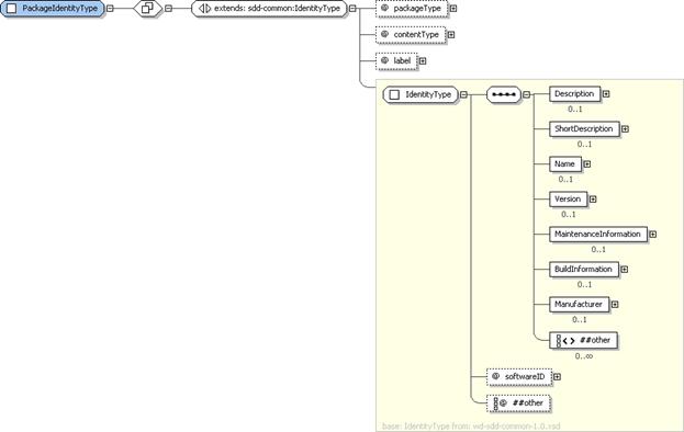
Figure 4: PackageIdentityType structure.
The software package described by the SDD can be identified
for humans and package management software using the properties in PackageIdentity. The PackageIdentity is not to be confused
with the identity of the deployed software, which is described in the resulting
resource elements of the deployment descriptor; see the ResultingResourceType section [4.8.1].
|
Name
|
Data Type
|
*
|
Description
|
|
|
[extends]
IdentityType
|
|
See the
IdentityType section for additional properties [3.4].
|
|
packageType
|
PackageTypeType
|
0..1
|
The type of the
package, for example, “baseInstall” or “maintenance”.
**default value=“baseInstall”.
|
|
contentType
|
xsd:QName
|
0..1
|
The type of
content provided by this package, for example, BIOS.
|
|
label
|
xsd:NCName
|
0..1
|
A programmatic
label for this package.
|
|
|
xsd:anyAttribute
|
0..*
|
|
See the IdentityType
section for details of the inherited attributes and elements [3.4].
§
packageType:
The package type is provided to aid consumer understanding of the type of
content contained in the package. A package can contain more than one type of
content. In this case, a single packageType
value should be selected that represents the primary content type as
determined by the SDD author. The SDD defines a set of enumeration values in PackageTypeType which are extendable by
the SDD author.
The enumerated types defined by the SDD are as follows:
·
baseInstall:
The value baseInstall indicates that
the package provides a complete installation of the solution. This package type
is associated with deployment descriptors that contain installable units with
installation artifacts that install the primary solution resources.
When packageType
is not specified, this is the default value.
·
baseUninstall:
The value baseUninstall indicates
that the package provides a complete uninstallation of the solution. This
package type is associated with deployment descriptors that contain installable
units with uninstall artifacts that remove the primary solution resources.
·
configuration:
The value configuration indicates
that the package configures the solution. This package type is associated with
deployment descriptors that contain configuration units with configuration
artifacts that configure the solution.
·
maintenance:
The value maintenance indicates that
the package fixes one or more problems in the solution. This package type is
associated with deployment descriptors that contain installable units with update
artifacts.
·
modification:
The value modification indicates that
the package modifies the function of the solution in some way such as by adding
new function. This package type is associated with deployment descriptors that
contain installable units with update artifacts.
·
replacement:
The value replacement indicates that
the package installs a solution that replaces a previous version of the solution.
Replacement MAY be associated with migration of data into the new solution
and/or with deletion of the replaced solution. When associated with migration
of data, installation or configuration artifacts within the solution package
would perform the migration. When associated with deletion of the replaced
solution, uninstall artifacts within the solution package would perform the
deletion. This package type is associated with deployment descriptors that contain
installable units with installation artifacts that deploy a set of resources that
replace the set of resources associated with a previous version of the solution.
·
localization:
The value localization indicates that
the package contains materials that localize deployed software for one or more
languages.
§
contentType:
The value of contentType is
determined by the SDD manufacturer to communicate a characteristic of the
package that MAY be used in the manufacturer’s package management system or
other manufacturer-specific tools that use the SDD. The SDD author chooses the
values; they are not defined in this specification.
§
label:
The label MAY be used as an index in a package management system. The SDD
author chooses the values; they are not defined in this specification.
3.4 IdentityType
Figure
5: IdentityType structure.
This
complex type provides identity information for the package as a whole, as well
as for content elements, which are portions of the package. Content elements
are the InstallableUnit,
LocalizationUnit, ConfigurationUnit, CompositeUnit and CompositeInstallable elements defined in the deployment descriptor.
|
Name
|
Data
Type
|
*
|
Description
|
|
Description
|
DisplayTextType
|
0..1
|
A verbose description of the package or
content element.
|
|
ShortDescription
|
DisplayTextType
|
0..1
|
A limited description of the package or
content element.
|
|
Name
|
DisplayTextType
|
0..1
|
A human-readable, translatable, name for
the package or content element.
|
|
Version
|
VersionType
|
0..1
|
The package or content element version.
|
|
MaintenanceInformation
|
MaintenanceInformationType
|
0..1
|
Information about package or content
element content used when the package contains maintenance.
|
|
BuildInformation
|
BuildInformationType
|
0..1
|
A manufacturer identifier for the build of
this package or content element. This property can be extended with
additional manufacturer-specific information about the build.
|
|
Manufacturer
|
ManufacturerType
|
0..1
|
Information about the manufacturer of the
package or content element.
|
|
|
xsd:any
|
0..*
|
|
|
softwareID
|
xsd:string
|
0..1
|
A manufacturer’s identification number for
the software created or updated by the package or content element.
|
|
|
xsd:anyAttribute
|
0..*
|
|
§
Description,
ShortDescription: These elements MAY be used to provide human-understandable
information. If used, they MUST provide a description of the package.
The Description
element MUST be defined if the ShortDescription
element is defined.
See the DisplayTextType
section for structure and additional usage details [4.14.3].
§
Name:
When the manufacturer of the SDD has a package management system, Name in PackageIdentity should correspond to the name of the package as
known in the package management system. Name
in a content element’s Identity should
correspond to the name of the unit of packaging, if it is known in the package management
system.
When
the PackageIdentity element is
defined, Name MUST be defined.
Software
packages that create software often have the same name as the deployed
software. Software packages that update software often have a name that
reflects the fact that the package is a maintenance package, differentiating it
from the base deployed software. The author of the software package that is
described by PackageIdentity
determines whether the Name is the
same as or different from the Name of
the deployed software.
See
the DisplayTextType section for
structure and additional usage details [4.14.3].
§
Version:
This is a packaging version. In PackageIdentity,
it is the version of the package as a whole. In content element identities, this
is the version of the unit of packaging represented by the content element. In
either case, the SDD author MAY choose to make this version correspond to the
version of a resulting or changed resource, but it should not be confused with
resource versions.
In
the case of a base install, version MAY be the same as the top level resulting
resource. In the case of a configuration package, version SHOULD NOT be the
same as the top level resulting resource.
See
the VersionType section for structure
and additional usage details [3.10].
§
MaintenanceInformation:
This is used when the package or content element describes the deployment of
maintenance.
See the MaintenanceInformationType
section for structure and additional usage details [3.5].
§
BuildInformation:
In PackageIdentity, this describes
the build of the package as a whole. In content element Identity, this describes the build of the artifact(s) and the content
element describing the artifact.
See the BuildInformationType
section for structure and additional usage details [3.7].
§
Manufacturer:
See the ManufacturerType section for
structure and additional usage details [3.8].
§
softwareID:
The software identified by softwareID
is the software whose deployment is described by the SDD. When the manufacturer
maintains software identifiers within a sales and distribution system, the softwareID SHOULD correspond to an
identifier for the software within that system. If a format for software
identifiers is not pre-existing within the manufacturer’s systems, a UUID
SHOULD be used for softwareID. When a
UUID is used, it MUST be unique within the domain in which the described
software is used.
Figure
6:
MaintenanceInformationType structure.
If
the package provides maintenance for deployed software, MaintenanceInformation declares information about the fix or fixes
provided. If the package content is a single fix, MaintenanceInformation describes the information about that one
fix. If the content is a collection of fixes—for
example, a fix pack—MaintenanceInformation
describes each of the fixes provided by the fix pack.
|
Name
|
Data
Type
|
*
|
Description
|
|
Severity
|
DisplayTextType
|
0..1
|
Severity of the maintenance content.
|
|
Category
|
DisplayTextType
|
0..*
|
Category of the maintenance content.
|
|
Supersedes
|
MaintenanceInformationType
|
0..*
|
A previously released fix that is
superseded by application of this maintenance.
|
|
Fix
|
FixIdentityType
|
0..*
|
An included fix.
|
|
|
xsd:any
|
0..*
|
|
§
Severity:
This value SHOULD correspond to a severity value used within the SDD provider’s
support system. It serves as a hint to the deployer about the urgency of
applying the described maintenance.
See
the DisplayTextType section for
structure and additional usage details [4.14.3].
§
Category:
These values SHOULD correspond to maintenance categories within the SDD
provider’s support system.
See
the DisplayTextType section for
structure and additional usage details [4.14.3].
§
Supersedes:
Superseded fixes are ones that fix a problem also fixed by the superseding
maintenance package or content element and therefore need not be applied.
This element does not indicate whether or
not the superseded fix needs to be removed. To indicate that the previous fix
must be removed before the superseding maintenance can be applied successfully;
the SDD author can create a requirement stating that the fix must not be
present.
Superseded fixes MAY include all the
information defined in MaintenanceInformationType.
At a minimum, a superseded fix MUST include at least one Fix element with the name of the superseded fix defined.
§
Fix: Fix elements provide information about
individual fixes provided by the maintenance content.
See
the FixIdentityType section for structure
and additional usage details [3.6].
Figure 7: FixIdentityType structure.
Elements of FixIdentityType
describe fixes that will be applied when the package is deployed or the content
element is applied.
|
Name
|
Type
|
*
|
Description
|
|
Name
|
xsd:NMTOKEN
|
1
|
A name for the
fix which is, at a minimum, unique within the scope of the resource fixed.
|
|
Description
|
DisplayTextType
|
1
|
A complete
description of the fix.
|
|
ShortDescription
|
DisplayTextType
|
0..1
|
An abbreviated
description of the fix.
|
|
Symptom
|
DisplayTextType
|
0..*
|
A symptom of the
problem fixed.
|
|
|
xsd:any
|
0..*
|
|
§
Name:
The Name element MUST provide a value
that uniquely identifies a fix within a scope defined by the manufacturer. This
is a name provided by the manufacturer that corresponds to the fix name as
understood in the deployment environment.
§
Description,
ShortDescription: These elements MAY be used to provide human-understandable
information. If used, they MUST provide a description of the fix.
The
Description element MUST be defined
if the ShortDescription element is
defined.
See
the DisplayTextType section for
structure and additional usage details [4.14.3].
§
Symptom:
Symptom strings can be used to correlate a fix with one or more experienced
problems.
See the DisplayTextType
section for structure and additional usage details [4.14.3].
Figure 8: BuildInformationType structure.
BuildInformationType
provides the type definition for the BuildInformation
element in package and content element identity. BuildInformation provides information about the creation of the
package and its parts.
|
Name
|
Type
|
*
|
Description
|
|
buildID
|
xsd:token
|
1
|
Identifies the
build of the package or package element.
|
|
|
xsd:anyAttribute
|
0..*
|
|
§
buildID:
The buildID attribute is an
identifier provided by the manufacturer and meaningful to developers that can
be used to identify a build of the defining element. This information MUST correspond
with information known in the manufacturer’s build environment. It is
traditionally used during problem determination to allow maintainers of the
software to determine the specifics of package creation. Inclusion of buildID in the SDD allows the end user
to provide this information to package maintainers, enabling them to correlate
the deployed software with a particular known build of the software.
3.8 ManufacturerType
Figure 9: ManufacturerType structure.
The SDD author can include information about the package manufacturer
that includes name, location and contact information such as the address of the
manufacturer’s Web site or telephone number.
|
Name
|
Type
|
*
|
Description
|
|
Name
|
DisplayTextType
|
1
|
A translatable
name for the manufacturer.
|
|
Location
|
LocationType
|
0..1
|
The address and
country of the manufacturer.
|
|
ContactInformation
|
DisplayTextType
|
0..1
|
Contact
information for the manufacturer.
|
|
|
xsd:any
|
0..*
|
|
§
Name: The value
provided in the Name element MUST be
an identifiable name of the manufacturer of the SDD.
See the DisplayTextType
section for structure and additional usage details [4.14.3].
§
Location: See
the LocationType section for
structure and additional usage details [3.9].
§
ContactInformation: This element
MAY provide additional contact information for the named manufacturer, such as
a support Web site address or a technical support telephone number.
See the DisplayTextType
section for structure and additional usage details [4.14.3].
Figure 10: LocationType structure.
LocationType supports inclusion of the
manufacturer’s address and country in package and content element identity.
|
Name
|
Type
|
*
|
Description
|
|
Address
|
DisplayTextType
|
0..1
|
The
manufacturer’s address.
|
|
Country
|
DisplayTextType
|
0..1
|
The
manufacturer’s country.
|
§
Address: This
is the mailing address or the physical address.
See the DisplayTextType
section for structure and additional usage details [4.14.3].
§
Country: Recording
the manufacturer’s country in the SDD provides information that may be of
interest in relation to import and export of software.
See the DisplayTextType
section for structure and additional usage details [4.14.3].
VersionType provides the type definition
for version elements in the package descriptor and deployment descriptor. It is
a simple type that is based on xsd:string with no further
restrictions. This means that versions in the SDD are represented simply as
strings. Because resource versions exist in the deployment environment, their
formats and semantics vary widely. For this reason, the format and semantics of
versions are not defined by this specification.

Figure 11: Contents structure.
ContentsType
is used in PackageDescriptor to
provide a list of one or more Content
elements.
|
Name
|
Type
|
*
|
Description
|
|
Content
|
ContentType
|
1..*
|
Describes
the physical contents of the software package.
|
§
Content: A
PackageDescriptor MUST contain a Contents element that is a list of one
or more Content elements.
See the ContentType
section for structure and additional usage details [3.12].

Figure 12: ContentType structure.
A software package includes one or more content files. ContentType defines the properties of a
content file included in the package descriptor. Content defined in the package
descriptor as part of the software package does not need to be physically
co-located. Each element MUST be in a location that can be identified by a URI.
The pathname attribute of each content
file defines a URI for accessing the file. Characteristics of the content files—such as their length, purpose and
character encoding—MAY be
declared in the package descriptor.
|
Name
|
Data Type
|
*
|
Description
|
|
ds:DigestMethod
|
ds:DigestMethodType
|
0..1
|
Specifies
the digest method applied to the file.
|
|
ds:DigestValue
|
ds:DigestValueType
|
0..1
|
Specifies
the Base64-encoded value of the digest of the file.
|
|
id
|
xsd:ID
|
1
|
An
identifier used in deployment descriptors to refer to the file definition in
the associated package descriptor.
|
|
pathname
|
xsd:anyURI
|
1
|
The absolute
or relative path of the content file including the file name.
|
|
purpose
|
ContentPurposeType
|
0..1
|
Associates a
purpose classification with a file.
**default
value=“content”
|
|
charEncoding
|
xsd:string
|
0..1
|
Specifies
the character encoding of the contents of the file.
|
|
length
|
xsd:nonNegativeInteger
|
0..1
|
Specifies
the size of the file in bytes.
|
|
|
xsd:anyAttribute
|
0..*
|
|
§
ds:DigestMethod,
ds:DigestValue: These values MAY be used to assist with file verification.
See the DigestInfoGroup
section for structure and additional usage details [3.13].
§
id: This
is the identifier for the content that is used as a reference in artifact
elements in the deployment descriptor.
The id
attribute may be useful to software that processes the SDD, for example, for
use in creating log and trace messages.
§
pathname:
pathname is used to access content in
the package. The path of the file MUST be a URI that specifies an absolute path
or a path relative to the location of the package descriptor. It MUST include
the file name.
§
purpose:
The purpose attribute enables the PackageDescriptor author to associate a
classification with a file. The classification identifies the file as having a
specific purpose. ContentPurposeType
defines a union of SDDContentPurposeType
with xsd:NCName. The purpose value MAY be chosen from one of the following values
enumerated in SDDContentPurposeType
or be a valid NCName value provided by the SDD author. If purpose is not specified, the default value is content.
Enumerated values for purpose are:
·
readMe: A
file with information about the package. An implementation may choose to
display this to a user as part of the deployment process.
·
endUserLicenseAgreement:
A file containing an end user license agreement. An implementation may choose
to display this to a user as part of the deployment process.
·
responseFile:
A file that contains input values for an operation.
·
deploymentDescriptor:
An XML file containing the DeploymentDescriptor
definition associated with the PackageDescriptor.
A valid PackageDescriptor MUST have exactly
one Content element with a purpose value of deploymentDescriptor.
·
packageDescriptor: Supports aggregation of packages. This
is used to reference a packageDescriptor
of an aggregated package.
·
descriptorLanguageBundle:
A file containing translations of text defined directly in the package
descriptor or its associated deployment descriptor.
·
content: A file used during deployment of
solution content. This is the
default value for purpose.
§
charEncoding:
This attribute need only be used for files that a run-time is required to
render. Common charEncoding values
include “ASCII”, “UTF-8”, “UTF-16” and “Shift_JIS”. For an extensive list of
character encodings, see [IANA-CHARSET].
§
length:
The file length MAY be used for simple file verification.
3.13 DigestInfoGroup

Figure 13: DigestInfoGroup structure.
When digest information is used to sign a content file, both
the digest method and the digest value MUST be provided.
§
ds:DigestMethod,
ds:DigestValue: ds:digestMethod
and ds:digestValue MAY be used to
digitally sign individual files. If files are signed, the digest value MUST be
calculated over the whole of each file.
See [XMLDSIG-CORE] for
details on the usage of ds:DigestMethod
and ds:DigestValue.
A solution package contains a deployment descriptor in
addition to a package descriptor. The deployment descriptor describes the
topology, selectability, inputs, requirements and conditions of the deployment.
The deployment descriptor is associated with a package descriptor and refers to
content files in that package descriptor.
4.1 DeploymentDescriptor
Figure 14: DeploymentDescriptor
structure.
DeploymentDescriptor
is the top level element of a deployment descriptor. The DeploymentDescriptor defines the information required to support
deployment of the package contents. This includes the Topology, which declares all of the resources that may participate
in deployment. It also includes one atomic content element or one or more CompositeInstallable content elements. Atomic content elements are InstallableUnit, ConfigurationUnit, or LocalizationUnit.
Atomic content elements define artifacts that can be processed to deploy
software resources. They are atomic because they cannot aggregate other content
elements. A CompositeInstallable
element is the root of a content element hierarchy that defines content that
performs the one deployment operation supported by the CompositeInstallable. A CompositeInstallable
can define base, selectable and localization content as well as the aggregation
of other content elements.
|
Name
|
Data Type
|
*
|
Description
|
|
Topology
|
TopologyType
|
1
|
Defines
resources that are required, created or modified by deployment.
|
|
InstallableUnit
|
InstallableUnitType
|
0..1
|
Defines content
that installs, updates and/or uninstalls resources. When an InstallableUnit
is defined, no ConfigurationUnit, LocalizationUnit or CompositeInstallable
elements can be defined.
|
|
ConfigurationUnit
|
ConfigurationUnitType
|
0..1
|
Defines
content that configures resources. When a ConfigurationUnit is defined, no
InstallableUnit, LocalizationUnit or CompositeInstallable elements can be
defined.
|
|
LocalizationUnit
|
LocalizationUnitType
|
0..1
|
Defines
content that installs, updates and/or uninstalls translated materials. When a
LocalizationUnit is defined, no InstallableUnit, ConfigurationUnit or
CompositeInstallable elements can be defined.
|
|
CompositeInstallable
|
CompositeInstallableType
|
0..*
|
Defines a
hierarchy of base, selectable and/or localization content used to perform one
deployment lifecycle operation. When one or more CompositeInstallable
elements are defined, no InstallableUnit, ConfigurationUnit or
LocalizationUnit elements can be defined.
|
|
Requisites
|
RequisitesType
|
0..1
|
A list of
references to SDD packages that can optionally be deployed to satisfy
deployment requirements of the defining SDD.
|
|
|
xsd:any
|
0..*
|
|
|
schemaVersion
|
xsd:string
|
1
|
The descriptor
complies with this version of the Solution Deployment Descriptor
Specification.
**fixed
value=“1.0”
|
|
descriptorID
|
UUIDType
|
1
|
Identifier of the
deployment descriptor for a particular set of deployable content.
|
|
lastModified
|
xsd:dateTime
|
1
|
The time the
descriptor was last modified.
|
|
descriptorLanguageBundle
|
xsd:token
|
0..1
|
The root name of
language bundle files containing translations for display text elements in
the deployment descriptor.
|
|
|
xsd:anyAttribute
|
0..*
|
|
§
Topology:
Topology provides a logical view of
all resources that may participate in any particular deployment. A resource can
participate by being required, created or modified by the deployment. A
required resource MAY also play the role of target resource, meaning that it
can process artifacts to perform some portion of the deployment. The resources
that actually participate in a particular deployment are determined by the user
inputs, selections and resource bindings provided during that deployment.
See the TopologyType
section for structure and additional usage details [4.2.1].
§
InstallableUnit,
ConfigurationUnit, LocalizationUnit, CompositeInstallable: A simple
software deployment that uses a single artifact for each supported deployment
operation MAY be described using an SDD that defines a single atomic content
element–InstallableUnit, ConfigurationUnit or LocalizationUnit.
A software deployment that requires multiple
artifacts, aggregates other deployment packages or has selectable content MAY be
described using an SDD that defines one or more CompositeInstallable elements. Each CompositeInstallable MUST describe one deployment lifecycle
operation for the package.
See the respective sections (InstallableUnitType [4.3.1], ConfigurationUnitType
[4.3.2], LocalizationUnitType
[4.13.2] and CompositeInstallableType
[4.9.1]) for structure and additional usage details.
§
Requisites:
When the package author chooses to provide deployment packages for required
software, those packages are described by Requisite
elements in Requisites.
Including requisite packages in the SDD package MAY provide
a convenient way for the deployer to satisfy one or more SDD requirements.
See the RequisitesType
section for structure and additional usage details [4.10.5].
§
schemaVersion,
descriptorID, lastModified,
descriptorLanguageBundle: These attributes can be useful to tooling that
manages, creates or modifies deployment descriptors and to tooling and
deployment software that displays information from the deployment descriptor to
humans.
See the DescriptorInfoGroup
section for structure and additional usage details [3.2].
4.2 Topology
The
SDD’s topology describes all the resources that may be required, created or
modified when any of the deployment operations supported by the SDD are
performed.
Primary
identifying characteristics of the resources can be defined in topology.
Constraints beyond these primary characteristics are not defined in topology; they
are defined in content elements that reference the resource definitions in
topology.
The
topology includes identification of hosts–hostedBy
relationships between resources. When both resources in that relationship
participate in a particular deployment, the relationship is considered a
requirement for that deployment.
It is
possible that only a subset of the resources described in topology will play a
role in a particular deployment. This is determined by the selection of content
elements for the particular deployment. The resources that are required,
created or modified by the content elements in scope for the deployment are the
ones that will participate in the deployment and so are associated with
resources in the deployment environment.
At
deployment time, definitions of the resources that participate in that
particular deployment are associated with actual resource instances in the
deployment environment. The mechanisms for associating resource definitions
with resource instances are not described by the SDD. The SDD metadata
describes the characteristics of the participating resources. Whether
associations of resource instances with matching characteristics are made by
user choice or entirely by software does not affect the success of the
deployment. Resource characteristics used when making this association include
those defined in topology plus all those defined in constraints on the resource
in the content elements that are in scope for the particular deployment.
Some
topologies are variable. That is, a particular set of logical resources of the
same type in the topology might be associated with different physical resource
instances or the same physical resource during deployment. In this case, a
separate logical resource definition is created in topology for each possible
physical resource instance. Uniqueness constraints can then be used to describe
the conditions under which the separate resources can be associated with a
single resource.
All
resource definitions in the SDD are in topology. All other descriptions of
resources in the SDD are references to the resource definitions in the
topology.
Figure 15: TopologyType structure.
The Topology element
defines one or more hierarchies of resource specifications that describe the resources
that MAY play a role in the deployment of the contents of the solution package.
These resource specifications do not identify specific resource instances in a
specific deployment environment. Instead, they are logical specifications of
resources that can be associated with specific resource instances in the
deployment environment for a particular deployment based on the described resource
identity characteristics. These resources have a role in a particular solution
deployment only when they are required, created or modified by a content
element, or referred to by a variable, in that particular solution deployment.
|
Name
|
Type
|
*
|
Description
|
|
Resource
|
ResourceType
|
1..*
|
The root of a
tree of resources that play a role in the solution.
|
|
|
xsd:any
|
0..*
|
|
§
Resource:
The SDD author’s decision to model a resource in the deployment environment as
a resource in the SDD depends on the need to know about that resource when
planning for deployment, aggregating, deploying and managing the resource
lifecycle using the SDD. All resources required by the solution SHOULD be
included. For all Requirements
declared in the SDD, resources MUST be specified. Resources referred to by ResultingResource or ResultingChange elements MUST also be
included. The more complete the SDD is, the more useful it will be in guiding
successful deployment.
See the ResourceType
section for structure and additional usage details [4.2.2].
4.2.2 ResourceType
Figure 16: ResourceType structure.
Elements of ResourceType—both the top level Resource elements and the HostedResource elements within the
resource hierarchy—make up the topology
of an SDD. Each Resource element declares,
at a minimum, the type of the resource. Values for resource type are not
defined by this specification. A core assumption of this specification is that
an understanding of specific resource types and resource characteristics are
shared by the deployment descriptor author and the deployment software. Therefore,
if the deployment descriptor author declares a new resource type, then
deployment software operating on the SDD needs to understand how to handle that
resource type.
In addition to defining type, the resource elements MAY specify
a name and other identity properties that can be used to identify instances of
the resource in the deployment environment. The resource identity elements, Name and Property, are optional and MAY be specified in content elements rather
than in topology. Identity properties used in the resource specification in
topology MUST be those that do not change during deployment, even when the
resource is updated. Because resource versions can often change during an
update, there is no version element in resource specifications in Topology. Values can be defined for resource
name and resource properties that help to identify the resource. These
represent the basic identity of the resource and are true for all uses of the
resource in the solution.
ResourceType
provides the type definition for the Resource
and HostedResource elements defined
in Topology. All resources MAY nest resource
definitions for resources that they host. To host a resource means to provide
the execution environment for that resource.
For example, an operating system provides the
execution environment for software, and a database engine provides the
execution environment for a database table. The operating system hosts the
software and the database engine hosts the database table.
Each resource in these hierarchies may play a role in
solution deployment.
Content elements determine a resource’s participation and role(s)
in a particular solution deployment. Content elements can refer to resources in
Topology in several ways. A resource
can be identified via xsd:IDREF:
- as
the target of the content element’s artifacts. A target resource is a
resource that is capable of processing a particular artifact. A target
resource is often, but not always, the host of the resources created by
the artifacts it processes.
For example, an operating system may be the target of
an artifact that is a zip file. When the files are unzipped, the file system
resource is the host of those files.
See the targetResourceRef attribute in the InstallableUnitType [4.3.1], ConfigurationUnitType
[4.3.2] and LocalizationUnitType
[4.13.2] sections.
- as
the required base for an update applied by the artifact referenced by the content
element.
See the RequiredBaseType section [4.7.8].
- as
the resource that will be created by deploying the artifact referenced by
the content element.
See the ResultingResourceType section [4.8.1].
- as
the resource that will be changed by deploying the artifact referenced by
the content element.
See the ResultingChangeType section [4.8.2].
- as
the localization base for translated materials. The localization base is
the resource that is localized by deploying the translated materials.
See the LocalizationBase element in the LocalizationUnitType
section [4.13.2].
- as a
required resource named in the content element’s Requirements.
See the RequirementsType section [4.7.1].
- to
establish a variable value from a resource property.
See the ResourcePropertyType section [4.6.12].
One resource MAY be referred to by any number of content
elements and can be identified to play any or all of the roles just listed. When
a content element participates in a particular solution deployment, the
resources it references participate in that solution deployment and are associated
with resource instances in the deployment environment.
|
Name
|
Type
|
*
|
Description
|
|
Description
|
DisplayTextType
|
0..1
|
A description of
the resource and its role in the solution described by the SDD.
|
|
ShortDescription
|
DisplayTextType
|
0..1
|
A short
description of the resource and its role.
|
|
Name
|
VariableExpressionType
|
0..1
|
The name of the
resource as known in the deployment environment.
|
|
Property
|
PropertyType
|
0..*
|
An identity
property of the resource.
|
|
HostedResource
|
ResourceType
|
0..*
|
A resource that
participates in the solution and that is hosted by the defining resource.
|
|
|
xsd:any
|
0..*
|
|
|
id
|
xsd:ID
|
1
|
An identifier of
the resource scoped to the descriptor.
|
|
type
|
ResourceTypeNameType
|
1
|
A well-known
resource type.
|
|
|
xsd:anyAttribute
|
0..*
|
|
4.2.2.2 ResourceType
Property Usage Notes
§
Description,
ShortDescription: If used, these elements MUST provide a human-readable description
of the resource.
The
Description element MUST be defined
if the ShortDescription element is
defined.
See the DescriptionGroup
section for structure and additional usage details [4.14.1].
§
Name:
The resource name is an identifying characteristic of the resource that correlates
with a name for the resource in the deployment environment.
The type of the Name
element, VariableExpressionType,
allows the resource name to be expressed as a simple string or in terms of a
user input parameter or other variable.
An example of a good use of a variable expression in Resource.Name is to make sure that the installation directory is hosted on a
file system that has sufficient space available for deployment. In this
example, the file system resource element would define a HostedResource element for the directory. The Name of the directory would be expressed as a variable expression
that refers to a user input parameter for installation location. Content
elements that use the installation directory would express a requirement on the
directory and on the file system with the additional constraint that the file
system have a certain amount of available space (to satisfy the consumption
constraints). The fact that both resources are required and that they are defined
with a hosts–hostedBy relationship in Topology,
means that the directory that is used must be the installation directory and it
must be hosted by a file system that meets the consumption constraint for available
space.
Only the Variable
elements defined in a top level content element can be used to define a
resource Name, because these are the
only variables visible within Topology.
If the name of a resource is changed during
deployment, for example, during an update, then the resource name SHOULD NOT be
included in the resource specification. Instead, the pre-update resource name SHOULD
be specified in the RequiredBase
element of the installable unit that provides the update, and the post-update
name SHOULD be specified in the ResultingResource
element of the same installable unit.
See the VariableExpressionType
section for structure and additional usage details [4.6.1].
§
Property:
Property elements SHOULD be used when
Name alone is not sufficient to
identify the resource. The property used represents an identifying
characteristic of a resource.
See the PropertyType
section for structure and additional usage details [4.2.3].
§
HostedResource:
A Resource MAY define HostedResource elements. Each HostedResource element is an instance of
ResourceType. When both the host and
the hosted resource participate in a particular solution deployment, the
associated resource instances selected for use during that deployment must have
a hosts relationship.
For example, a Web application declared to be hosted
on a Web server must be hosted on the instance of the Web server that is
selected for use during the deployment.
If only the host resource is identified by the DeploymentDescriptor’s content elements as
participating in the solution, then there is no assumption that the hosted
resource exists.
§
id:
The id attribute uniquely identifies
the resource element within the DeploymentDescriptor.
This id value is used by other
elements in the DeploymentDescriptor
to refer to this resource. This value is created by the descriptor author.
The id
attribute may be useful to software that processes the SDD, for example, for
use in creating log and trace messages.
§
type:
The type attribute defines the class
of resource. The value of type
correlates with the resource type known for the resource in the deployment
environment. ResourceTypeNameType
restricts type to valid xsd:QNames. The values for type are not defined by this specification. Creators of DeploymentDescriptors rely on knowledge
of resource types that are understood by supporting infrastructure in the
target environment. To honor the descriptor author’s intent, the deploying
infrastructure must be able to discover the existence of resources of the types
defined in the SDD; the values of the resource’s properties; and the existence
and type of resource relationships. The deploying infrastructure also needs to
understand how to use the artifact types associated with the resource type to
create, modify and delete the resource.
4.2.3 PropertyType
Figure 17: PropertyType
structure.
PropertyType
provides the type definition for elements used to declare an identity property
of a resource, namely, the Property
elements of Resource and HostedResource in Topology. It also provides the type definition for Property elements in Relationship and RelationshipConstraint.
4.2.3.1 PropertyType
Property Summary
|
Name
|
Type
|
*
|
Description
|
|
PropertyName
|
xsd:QName
|
1
|
The
property name.
|
|
Value
|
VariableExpressionType
|
1
|
The
property value.
|
|
|
xsd:anyAttribute
|
0..*
|
|
4.2.3.2 PropertyType
Property Usage Notes
§
PropertyName:
The PropertyName MAY be used to provide
additional identification for the resource in the deployment environment.
The PropertyName
MAY be used to provide constraints on the configuration of a resource.
§
Value:
Evaluation of the Value expression
provides the value of the property.
See
the VariableExpressionType section
for structure and additional usage details [4.6.1].
Figure
18: ResultingPropertyType structure.
ResultingPropertyType provides the type
definition for elements used to declare an identity property of a resulting resource
or to declare a configuration change to a resource property which results from
deployment of an artifact.
4.2.4.1 ResultingPropertyType
Property Summary
|
Name
|
Type
|
*
|
Description
|
|
PropertyName
|
xsd:string
|
1
|
The resulting property name.
|
|
Value
|
VariableExpressionType
|
1
|
The resulting property value.
|
|
|
xsd:anyAttribute
|
0..*
|
Additional attributes of the resulting
property.
|
4.2.4.2 ResultingPropertyType
Property Usage Notes
§
PropertyName:
The PropertyName MAY be used to
provide additional identification for the resource in the deployment
environment.
The
PropertyName MAY be used to declare a
configuration change to a resource.
§
Value:
Evaluation of the Value expression
provides the value of the resulting property.
See
the VariableExpressionType section
for structure and additional usage details [4.6.1].
The
package descriptor defines package content that includes artifacts whose
processing results in deployment of the software package. The deployment
descriptor defines metadata associated with those artifacts. The metadata
includes conditions, requirements, results, inputs, outputs and completion
actions. Metadata throughout the deployment descriptor is associated with
package content in the definition of atomic content elements. The atomic content
elements are InstallableUnit, ConfigurationUnit and LocalizationUnit. These are the only
content elements that define Artifacts elements.
Artifact elements identify an artifact
file or set of files defined in package content whose processing will perform
all or a portion of the deployment for a particular deployment lifecycle
operation. The name of the artifact element indicates the operation supported
by the artifact. Names of the artifact elements are created by prefixing
“Artifacts” with the operation name. The artifacts defined for use in the SDD
are InstallArtifact, UpdateArtifact, UndoArtifact, UninstallArtifact,
RepairArtifact and ConfigArtifact.
Artifact elements define the inputs and
outputs, substitution values and types associated with the artifact files. The
content element’s target resource, identified by targetResourceRef, processes the artifact files with the defined
inputs to perform deployment operations. Examples of artifact types include zip
files, rpm files and executable install files. Artifact types are not defined
by this specification. The artifact types defined in the SDD need to be
understood by software that processes the SDD.
There
MAY be multiple atomic content elements within a composite installable that
describe the deployment of multiple resources as part of a single software
deployment or there MAY be a single atomic content element (singleton) in the
deployment descriptor that describes the entirety of a simple deployment. When an atomic content element is used in
a CompositeInstallable, it MUST define
exactly one artifact. When an atomic content element is a singleton, it MUST
define at least one artifact element and MAY define one of each type of
artifact element allowed for its type. The inclusion of an artifact element in
a singleton atomic content element implies support for the associated
operation.
For
example, a singleton ConfigurationUnit
that defines a ConfigArtifact
associates a configure operation with the ConfigArtifact.
Similarly, an SDD with a singleton InstallableUnit
that defines an InstallArtifact and
an UpdateArtifact associates an install operation with the InstallArtifact and an update operation with the UpdateArtifact.
When
an atomic content element is defined within a CompositeInstallable hierarchy, its one artifact MUST support the
single top level operation associated with the CompositeInstallable. The single artifact defined need not be an
artifact for the operation defined for the CompositeInstallable.
For
example, in a CompositeInstallable that
defines metadata for an update
operation, there may be one InstallableUnit
that defines an InstallArtifact element
and another InstallableUnit that
defines an UpdateArtifact element.
Both of these artifacts are used when performing the overall update operation defined for the CompositeInstallable.
Figure 19: InstallableUnitType
structure.
The InstallableUnit
element is an atomic content element that defines artifacts that install or
update software and defines requirements for applying those artifacts. It may
also define artifacts that undo an update or that uninstall or repair existing
software.
|
Name
|
Type
|
*
|
Description
|
|
Identity
|
IdentityType
|
0..1
|
Human-understandable
identity information about the InstallableUnit.
|
|
Condition
|
ConditionType
|
0..1
|
A condition that
determines if the content element is relevant to a particular deployment.
|
|
Variables
|
VariablesType
|
0..1
|
Variables for use
within the InstallableUnit’s requirements and artifact definitions.
|
|
RequiredBase
|
RequiredBaseType
|
0..1
|
A resource that
will be updated when the InstallableUnit’s UpdateArtifact is processed.
|
|
Requirements
|
RequirementsType
|
0..1
|
Requirements that
must be met prior to successful processing of the InstallableUnit’s
artifacts.
|
|
Languages
|
LanguagesType
|
0..1
|
Languages
supported by the InstallableUnit.
|
|
Completion
|
CompletionType
|
0..*
|
Describes
completion actions such as restart and the conditions under which the action
is applied.
|
|
ResultingResource
|
ResultingResourceType
|
0..*
|
A resource that
will be installed or updated by processing the InstallableUnit’s artifacts.
|
|
ResultingChange
|
ResultingChangeType
|
0..*
|
A resource that
will be configured by processing the InstallableUnit’s artifacts.
|
|
Artifacts
|
InstallationArtifactsType
|
1
|
The set of
artifacts associated with the InstallableUnit.
|
|
|
xsd:any
|
0..*
|
|
|
id
|
xsd:ID
|
1
|
An identifier for
the InstallableUnit scoped to the deployment descriptor.
|
|
targetResourceRef
|
xsd:IDREF
|
1
|
Reference to the
resource that can process the InstallableUnit’s artifacts.
|
|
|
xsd:anyAttribute
|
0..*
|
|
§
Identity:
The InstallableUnit’s Identity element defines human-understandable
information that reflects the identity of the solution as understood by the end
user of the solution.
If
the InstallableUnit defines a
resulting resource, the Identity of
the InstallableUnit SHOULD reflect
the identity of the resulting resource.
When
the InstallableUnit is the only
content element in the deployment descriptor, its Identity MAY define values that are the same as the corresponding PackageIdentity element values.
This would be useful, for example, in a case where
the package is known by the same name as the resource created by the InstallableUnit.
See
the IdentityType section for structure
and additional usage details [3.4].
§
Condition:
A Condition is used when the InstallableUnit’s content should be deployed
only when certain conditions exist in the deployment environment.
For example, one InstallableUnit
may be applicable only when the operating system resource is resolved to a Linux®
operating system during deployment. The InstallableUnit
would define a Condition stating that
the type of the operating system must be Linux for the InstallableUnit to be considered in scope for a particular
deployment.
See
the ConditionType section for structure
and additional usage details [4.5.1].
§
Variables:
An InstallableUnit’s Variables
element defines variables that are used in the definition of the InstallableUnit’s requirements and in parameters
and properties passed to the InstallableUnit’s
target resource.
When
the deployment descriptor defines a single InstallableUnit
at the top level, that is, not inside a CompositeInstallable,
the variables it defines MAY be referred to by any element under Topology.
See
the VariablesType section for structure
and additional usage details [4.6.3].
§
Languages:
When translated materials are deployed by the InstallableUnit’s artifacts, the languages of the translations are
listed in Languages.
See the LanguagesType
section for structure and additional usage details [4.13.6].
§
RequiredBase:
When an InstallableUnit can be used
to update resources, the RequiredBase
element identifies the resources that can be updated.
See
the RequiredBaseType section for structure
and additional usage details [4.7.8].
§
Requirements:
Requirements specified in an InstallableUnit identify requirements
that must be met prior to successful processing of the InstallableUnit’s artifacts.
See
the RequirementsType section for structure
and additional usage details [4.7.1].
§
Completion:
A Completion element MUST be included
if the artifact being processed requires a system operation such as a reboot or
logoff to occur to function successfully after deployment or if the artifact
executes a system operation to complete deployment of the contents of the
artifact.
There MUST be an artifact associated with the
operation defined by a Completion
element.
For example, if there is a Completion element for the install
operation, the InstallableUnit must
define an InstallArtifact.
See
the CompletionType section for structure
and additional usage details [4.3.14].
§
ResultingResource:
An InstallableUnit’s ResultingResource element identifies the
resources in Topology that will be installed
or updated when the InstallableUnit’s artifacts
are processed.
See
the ResultingResourceType section for
structure and additional usage details [4.8.1].
§
ResultingChange:
Multiple content elements within the SDD MAY specify the same resource in their
ResultingChange elements. In this
case each content element is capable of modifying the configuration of that
resource.
An example use of the ResultingChange element is to understand whether or not one content
element can satisfy the requirements specified in another content element.
See
the ResultingChangeType section for structure
and additional usage details [4.8.2].
§
Artifacts:
When the InstallableUnit is a
singleton defined outside of a CompositeInstallable,
it MUST define at least one artifact element and MAY define one of each type of
artifact element allowed for its type. The inclusion of an artifact element in
a singleton InstallableUnit implies
support for the associated operation.
When the InstallableUnit
is defined within a CompositeInstallable,
it MUST define exactly one artifact. The artifact defined MAY be any artifact
allowed in an InstallableUnit and it
MUST support the single top level operation defined by the CompositeInstallable. This does not mean the operation associated
with the artifact has to be the same as the one defined by the CompositeInstallable.
For example, an update of a resource may be required
to support an install of the overall solution, in which case the InstallableUnit would define an UpdateArtifact to support the top level install operation.
See the InstallationArtifactsType
section for structure and additional usage details [4.3.4].
§
id: The
id attribute is referenced in features
to identify an InstallableUnit
selected by the feature and Dependency
elements to indicate a dependency on processing of the content element.
The id
attribute may be useful to software that processes the SDD, for example, for
use in creating log and trace messages.
§
targetResourceRef:
The targetResourceRef attribute
identifies the resource that will process the InstallableUnit’s artifacts.
The
resources created or modified by artifact processing are frequently, but not
necessarily, hosted by the target resource.
This
value MUST match an id of a resource
element in Topology.
The
target may be a resource that has not yet been created. In this case, there is
a dependency on the complete installation of the target resource prior to applying
the InstallableUnit. This dependency
MUST be represented in a Dependency
element within Requirements that
apply to the InstallableUnit.
Figure 20: ConfigurationUnitType
structure.
The ConfigurationUnit
element defines artifacts that configure one or more existing resources. It
also defines the requirements for applying those artifacts. It MUST NOT install,
update, or uninstall resources.
|
Name
|
Type
|
*
|
Description
|
|
Identity
|
IdentityType
|
0..1
|
Human-understandable
identity information about the ConfigurationUnit.
|
|
Condition
|
ConditionType
|
0..1
|
A condition that
determines if the content element is relevant to a particular deployment.
|
|
Variables
|
VariablesType
|
0..1
|
Variables for use
within the ConfigurationUnit’s requirement and artifact definitions.
|
|
Requirements
|
RequirementsType
|
0..1
|
Requirements that
must be met prior to successful processing of the ConfigurationUnit’s
artifacts.
|
|
Completion
|
CompletionType
|
0..*
|
Describes
completion actions such as restart and the conditions under which the action
is applied.
|
|
ResultingChange
|
ResultingChangeType
|
0..*
|
A definition of
changes made to a resource that is configured by processing the
ConfigurationUnit’s ConfigArtifact.
|
|
Artifacts
|
ConfigurationArtifactsType
|
1
|
The artifact
associated with the ConfigurationUnit.
|
|
|
xsd:any
|
0..*
|
|
|
id
|
xsd:ID
|
1
|
An identifier for
the ConfigurationUnit scoped to the deployment descriptor.
|
|
targetResourceRef
|
xsd:IDREF
|
1
|
Reference to the
resource that can process the ConfigurationUnit’s artifacts.
|
|
|
xsd:anyAttribute
|
0..*
|
|
§
Identity:
The ConfigurationUnit’s Identity element defines
human-understandable information that reflects the identity of the provided
configuration as understood by the end user of the solution. Identity has elements that are common
with elements in the corresponding PackageDescriptor’s
PackageIdentity element, for example,
Name and Version. The values of these common elements SHOULD be the same as
the corresponding PackageIdentity
element values.
See the IdentityType
section for structure and additional usage details [3.4].
§
Condition:
A Condition is used when the deployment
of configuration content is dependent on the existence of certain conditions in
the deployment environment.
For example, a package that has one configuration
artifact that creates a database table for one database product and a different
artifact that creates a table for a different database product would have two
configuration units, each with a condition on the associated database product.
See the ConditionType
section for structure and additional usage details [4.5.1].
§
Variables:
A ConfigurationUnit’s Variables
element defines variables that are used in the definition of requirements and
artifact parameters.
When
the deployment descriptor defines a single ConfigurationUnit
at the top level, that is, not inside a CompositeInstallable,
the variables it defines MAY be referred to by any element under Topology.
See the VariablesType
section for structure and additional usage details [4.6.3].
§
Requirements:
Requirements specified in a ConfigurationUnit identify requirements
that MUST be met prior to successful processing of the ConfigurationUnit’s artifacts.
See the RequirementsType
section for structure and additional usage details [4.7.1].
§
Completion:
A Completion element MUST be included
if the artifact being processed requires a system operation such as a reboot or
logoff to occur to function successfully after deployment or if the artifact
executes a system operation to complete deployment of the contents of the
artifact.
There MUST be an artifact associated with the
operation defined by a Completion
element.
For example, if there is a Completion element for the configure
operation, the ConfigurationUnit must
define a ConfigArtifact.
See the CompletionType
section for the structure and additional usage details [4.3.14].
§
ResultingChange:
Configuration changes made when the configuration artifact is processed SHOULD be
declared here. This information may be necessary when the SDD is aggregated
into another SDD and the resulting change satisfies a constraint in the
aggregation. The information declared here can be compared with resource
constraints to determine if application of the ConfigurationUnit will satisfy the constraint.
See
the ResultingChangeType section for structure
and additional usage details [4.8.2].
§
Artifacts:
When the ConfigurationUnit is a
singleton defined outside of a CompositeInstallable,
it MUST define at least one artifact element. The inclusion of an artifact
element in a singleton ConfigurationUnit
implies support for the associated operation.
When the ConfigurationUnit
is defined within a CompositeInstallable,
it MUST define exactly one artifact. The artifact defined MUST be a ConfigArtifact and it MUST support the
single top level operation defined by the CompositeInstallable.
See the ConfigurationArtifactsType
section for structure and additional usage details [4.3.5].
§
id: The
id attribute may be useful to
software that processes the SDD, for example, for use in creating log and trace
messages.
§
targetResourceRef:
The targetResourceRef attribute
identifies the resource in Topology that
will process the ConfigurationUnit’s
artifacts to configure the resources identified by the ConfigurationUnit’s ResultingChange
definition.
This
value MUST match an id of a resource
element in Topology.
Figure
21: ArtifactType structure.
ArtifactType elements define the files,
arguments and other information required to perform a particular deployment
operation. Every artifact that can be defined in a content element is an
instance of ArtifactType. These are InstallArtifact, UpdateArtifact,
UndoArtifact, UninstallArtifact, RepairArtifact and ConfigArtifact.
4.3.3.1 ArtifactType
Property Summary
|
Name
|
Type
|
*
|
Description
|
|
Arguments
|
ArgumentListType
|
0..1
|
Arguments used during processing of the
artifact.
|
|
OutputVariables
|
OutputVariableListType
|
0..1
|
Variables whose values are set during
processing of the artifact.
|
|
AdditionalContent
|
AdditionalContentType
|
0..*
|
Additional content files that are part of
the artifact.
|
|
|
xsd:any
|
0..*
|
|
|
contentRef
|
xsd:token
|
0..1
|
The primary artifact file. Not used if
resourceRef is used.
|
|
resourceRef
|
xsd:IDREF
|
0..1
|
The resulting resource representing the artifact
file. Not used if contentRef is used.
|
|
type
|
ArtifactTypeNameType
|
0..1
|
Type of the primary artifact file.
|
|
weight
|
xsd:positiveInteger
|
0..1
|
The time required to process this artifact
relative to all other artifacts in the SDD.
|
|
|
xsd:anyAttribute
|
0..*
|
|
4.3.3.2 ArtifactType
Property Usage Notes
§
Arguments:
Inputs to the processing of the artifact MUST be specified by defining an Arguments element. All required inputs MUST
be included in the arguments list. There are no implied arguments.
For
example, there is no implication that the selected required resource instances
will be passed with an InstallArtifact
on the install operation. If knowledge of those selections is required,
instance identifiers should be passed as arguments.
When
one Argument refers to the OutputVariable of another artifact, the
output value must be available at the time of processing the dependent
artifact.
For
example, an artifact in a content element that is conditioned on the operating
system being Linux should not refer to the output of an artifact in a content
element conditioned on the operating system being Windows™.
A Dependency requirement MUST be defined
between the content elements to indicate that the artifact that defines the
output variable is a pre-requisite of the content element with the dependent
artifact.
See
the ArgumentListType section for structure
and additional usage details [4.3.8].
§
OutputVariables:
OutputVariables are variables whose
values are set by artifact processing.
OutputVariables can also be useful in
log and trace messages.
See
the OutputVariableListType section
for structure and additional usage details [4.3.10].
§
AdditionalContent:
AdditionalContent elements MUST be
defined when supporting files are needed by the artifact for this operation.
The content file reference is specified via the contentRef attribute of AdditionalContent.
See
the AdditionalContentType section for
structure and additional usage details [4.3.12].
§
contentRef:
The value MUST be a reference to the id
of the primary artifact file defined in a Content
element in the package descriptor.
Note
that it is valid to have no artifact file and drive the operation from
arguments alone.
When
more than one artifact file is needed, contentRef
points to the primary artifact file and AdditionalContent.contentRef points to any other files
used during application of the content element.
When resourceRef
is defined, contentRef MUST NOT be
defined.
§
resourceRef:
Sometimes, artifact files are created during a deployment rather than being contained
in the package.
For
example, some install programs create an uninstall program when the software is
deployed. The uninstall program is the artifact file that is needed by the UninstallArtifact, but is created by,
but not contained in, the package. In this case, the created artifact file is
represented as a ResultingResource.
An Artifact element that defines resourceRef identifies the resulting
resource as its artifact file.
When
contentRef is defined, resourceRef MUST NOT be defined.
The value MUST reference the id of a resource element in Topology.
§
type:
The type attribute identifies the
format of the artifact file or files. When there is no artifact file
identified, type MAY be left
undefined. If there is an artifact file or additional files defined, type MUST be defined.
Values for this attribute are not defined by
this specification. ArtifactTypeNameType
restricts type to valid xsd:QNames.
§
weight:
Defining weights for all artifacts and referenced packages in an SDD provides
useful information to software that manages deployment. The weight of the artifact
refers to the relative time taken to deploy the artifact with respect to other artifacts
and referenced packages in this SDD.
For
example, if the artifact takes three times as long to deploy as another artifact
whose weight is “2”, then the weight would be “6”. The weight numbers have no
meaning in isolation and do not describe actual time elapsed. They simply
provide an estimate of relative time.
Figure
22:
InstallationArtifactsType structure.
InstallationArtifactsType provides the
type definition for the Artifacts
element of InstallableUnit and LocalizationUnit. At least one Artifact element MUST be defined. Within
a CompositeInstallable definition,
exactly one Artifact element MUST be
defined.
4.3.4.1 InstallationArtifactsType
Property Summary
|
Name
|
Type
|
*
|
Description
|
|
InstallArtifact
|
ArtifactType
|
0..1
|
Artifact for install operation.
|
|
UpdateArtifact
|
ArtifactType
|
0..1
|
Artifact for update operation.
|
|
UndoArtifact
|
ArtifactType
|
0..1
|
Artifact for undo operation.
|
|
UninstallArtifact
|
ArtifactType
|
0..1
|
Artifact for uninstall operation.
|
|
RepairArtifact
|
ArtifactType
|
0..1
|
Artifact for repair operation.
|
|
|
xsd:any
|
0..*
|
|
4.3.4.2 InstallationArtifactsType
Property Usage Notes
§
InstallArtifact:
The InstallArtifact element declares
deployment information sufficient to enable the target resource to perform an
install using the named artifact files. The ResultingResource
and ResultingChange elements describe
the characteristics of the new or modified resource(s).
See
the ArtifactType section for structure
and additional usage details [4.3.3].
§
UpdateArtifact:
The UpdateArtifact element declares
deployment information sufficient to enable the target resource to perform an
update using the named artifact files. The RequiredBase
element defines the resource(s) that can be updated. The ResultingResource and ResultingChange
elements describe the updated characteristics of the resource(s).
See
the ArtifactType section for structure
and additional usage details [4.3.3].
§
UndoArtifact:
The UndoArtifact element declares
deployment information sufficient to enable the target resource to undo an update.
This undo will put the resource back to a previous level.
The update that can be undone is described
in the RequiredBase element. The ResultingResource definition can be used
to describe the state of the resource(s) after the undo completes.
See
the ArtifactType section for structure
and additional usage details [4.3.3].
§
UninstallArtifact:
The UninstallArtifact element
declares deployment information sufficient to enable the target resource to perform
an uninstall.
If an InstallArtifact
is defined in the same InstallableUnit,
the ResultingResource element defines
the resource(s) that will be uninstalled.
When an UninstallArtifact
is the only artifact defined for an InstallableUnit,
the RequiredBase MUST be defined to
declare the resource(s) that will be uninstalled. The ResultingResource element MUST be left blank because the result of
the uninstall is that the resource(s) are removed.
See
the ArtifactType section for structure
and additional usage details [4.3.3].
§
RepairArtifact:
The RepairArtifact element declares
deployment information sufficient to enable the target resource to repair an
installation.
If
an InstallArtifact is defined in the
same InstallableUnit, the ResultingResource element defines the
resource(s) that will be repaired.
When
a RepairArtifact is the only artifact
defined for an InstallableUnit, the RequiredBase MUST be defined to declare
the resource(s) that will be repaired.
See
the ArtifactType section for structure
and additional usage details [4.3.3].
Figure
23:
ConfigurationArtifactsType structure.
ConfigurationArtifactsType provides the
type definition for the Artifacts
element of ConfigurationUnit.
4.3.5.1 ConfigurationArtifactsType
Property Summary
|
Name
|
Type
|
*
|
Description
|
|
ConfigArtifact
|
ArtifactType
|
0..1
|
Artifact for configure operation.
|
|
|
xsd:any
|
0..*
|
|
4.3.5.2 ConfigurationArtifactsType
Property Usage Notes
§
ConfigArtifact:
The ConfigArtifact element declares
deployment information sufficient to allow the target resource to configure the
resources identified in the content element’s ResultingChange elements.
See
the ArtifactType section for
structure and additional usage details [4.3.3].
This
simple type extends the xsd:list type
as defined in [XSD], and adds the restriction that each value in the
list must be one of the operations from the enumeration defined by OperationType [4.3.7].
4.3.7 OperationType
Operations
are used in the SDD to associate requirements and completion actions with
particular artifacts.
For
example, when a requirement defines an operation
attribute with value undo, it is a
statement that the requirement must be met prior to processing of the undo
artifact.
OperationType enumerates the basic resource
lifecycle operations that use the content and information defined in the SDD to
change the state of the resources being installed, updated, or configured.
4.3.7.1 OperationType
Property Usage Notes
Elements
and attributes of OperationType MUST
be set to one of the following values:
§
configure:
Uses the ConfigArtifact to perform
configuration actions on a resource.
§
install:
Uses the InstallArtifact to install
resources.
§
repair:
Uses the RepairArtifact to repair an
installation.
§
undo:
Uses the UndoArtifact to restore a
resource to the state before the most recent update was applied.
§
update:
Uses the UpdateArtifact to update an
existing instance of a resource, as specified by the required base.
§
use:
Associates a requirement or completion action with use of the deployed software
resources. Setting the operation attribute to use indicates that the requirement or completion action is not
associated with an artifact.
§
uninstall:
Uses the UninstallArtifact to
uninstall a resource.

Figure
24: ArgumentListType
structure.
Each
artifact MAY optionally include an Arguments
element whose type is provided by ArgumentListType.
This simply defines a list of Argument
elements.
4.3.8.1 ArgumentListType
Property Summary
|
Name
|
Type
|
*
|
Description
|
|
Argument
|
ArgumentType
|
1..*
|
An input to artifact processing.
|
4.3.8.2 ArgumentListType
Property Usage Notes
§
Argument:
An argument value is a variable expression used to define a fixed value for the
argument or to define a value in terms of one of the variables visible to the
artifact.
See
the ArgumentType section for
structure and additional usage details [4.3.9].
Figure
25: ArgumentType structure.
ArgumentType provides the type
definition for Argument elements in
artifacts [4.3.3]. This complex type is used to declare the argument
name and optionally include a value for that argument.
4.3.9.1 ArgumentType
Property Summary
|
Name
|
Type
|
*
|
Description
|
|
name
|
VariableExpressionType
|
1
|
The argument name.
|
|
value
|
VariableExpressionType
|
0..1
|
The argument value.
|
|
required
|
xsd:boolean
|
0..1
|
Indicates that the argument value must result in a valid
expression for each particular deployment.
**default value=“true”
|
|
|
xsd:anyAttribute
|
0..*
|
|
4.3.9.2 ArgumentType
Property Usage Notes
§
name:
Evaluation of the name expression
produces the name of the argument. This can be useful for arguments with only a
name, for example, those that are not name-value pairs.
When the argument name alone is sufficient
to communicate its meaning, the argument value SHOULD be omitted.
See the VariableExpressionType
section for structure and additional usage details [4.6.1].
§
value:
Evaluation of the value expression
provides the value of the argument.
The variable expression MAY be used to
define a fixed value for the argument or to define a value in terms of one of
the variables visible to the artifact.
See the VariableExpressionType
section for structure and additional usage details [4.6.1].
§
required:
In cases where the argument should be ignored when the value expression is not
valid for a particular deployment, set required to "false".

Figure 26:
OutputVariableListType structure.
An
artifact can set variables. The variables set by the artifact are defined in
the artifact’s OutputVariables.
4.3.10.1 OutputVariableListType
Property Summary
|
Name
|
Type
|
*
|
Description
|
|
OutputVariable
|
OutputVariableType
|
1..*
|
An
output from artifact processing.
|
4.3.10.2 OutputVariableListType
Property Usage Notes
§
OutputVariable:
This is the definition of the variable, not a reference to a variable defined
elsewhere.
See the OutputVariableType
section for structure and additional usage details [4.3.11].
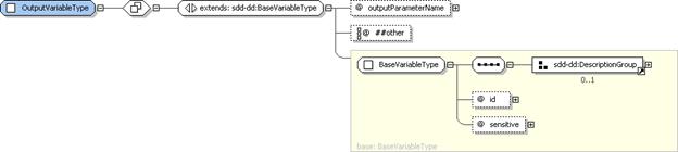
Figure 27: OutputVariableType
structure.
Output
variables are variables whose value is set by artifact processing. OutputVariableType extends BaseVariableType and so has all of the
attributes defined there, including an id
attribute that is used to refer to the output variable within the SDD. Output
variables can be useful in log and trace messages.
4.3.11.1 OutputVariableType
Property Summary
|
Name
|
Type
|
*
|
Description
|
|
|
[extends]
BaseVariableType
|
|
See
the BaseVariableType section for additional properties [4.6.2].
|
|
outputParameterName
|
xsd:NCName
|
0..1
|
An
output from artifact processing.
|
|
|
xsd:anyAttribute
|
0..*
|
|
4.3.11.2 OutputVariableType
Property Usage Notes
See the BaseVariableType
section for details of the inherited attributes and elements [4.6.2].
§
outputParameterName:
This is the name of the output variable as understood within the artifact
processing environment. The output value is associated with the output
variable’s id. The SDD author uses
this id within the SDD to refer to
this output value.
Figure 28: AdditionalContentType
structure.
When artifact processing requires more than
a single file, the artifact declaration includes information about the
additional files needed. AdditionalContentType
provides the type definition. Additional content MAY include input files that
need to be edited to include values received as input to a particular solution
deployment. In this case, the additional file can include a Substitution element.
4.3.12.1 AdditionalContentType
Property Summary
|
Name
|
Type
|
*
|
Description
|
|
Substitution
|
SubstitutionType
|
0..*
|
A
value to substitute into the file.
|
|
|
xsd:any
|
0..*
|
|
|
contentRef
|
xsd:token
|
1
|
A reference to the content element’s id defined in
the package descriptor.
|
|
type
|
ArtifactTypeNameType
|
0..1
|
Type
of the additional artifact file.
|
|
|
xsd:anyAttribute
|
0..*
|
|
4.3.12.2 AdditionalContentType
Property Usage Notes
§
Substitution:
The Substitution element supports the
use of files that require some editing before they can be used in artifact
processing. The definitions in this element support placement of values
determined during a particular deployment into the file identified by the contentRef attribute.
See the SubstitutionType
section for structure and additional usage details [4.3.13].
§
contentRef:
The contentRef attribute points back
to the package descriptor for information about the physical file. This value
MUST match an id of a content element
in the package descriptor.
§
type:
The type attribute identifies the
format of the additional file. Values for this attribute are not defined by
this specification. ArtifactTypeNameType
restricts values of type to valid xsd:QNames.
Figure 29: SubstitutionType
structure.
SubstitutionType
provides the type definition for the Substitution
element in AdditionalContent
declarations. It enables declaration of patterns in the file and the values
that should replace the patterns before the file is used in artifact
processing.
4.3.13.1 SubstitutionType
Property Summary
|
Name
|
Type
|
*
|
Description
|
|
Pattern
|
xsd:string
|
1
|
The
search pattern in the file that needs to be substituted.
|
|
Value
|
VariableExpressionType
|
1
|
The
value to be substituted in the file.
|
|
limit
|
xsd:positiveInteger
|
0..1
|
The
number of substitutions that should be made.
|
|
required
|
xsd:boolean
|
0..1
|
Indicates
that substitution's value must result in a valid expression for each
particular deployment.
**default
value=“true”
|
|
|
xsd:anyAttribute
|
0..*
|
|
4.3.13.2 SubstitutionType
Property Usage Notes
§
Pattern:
This is the string that will be replaced with the value when found in the file.
§
Value:
Evaluation of the variable expression results in the value that will be
substituted for the pattern.
See the VariableExpressionType
section for structure and additional usage details [4.6.1].
§
limit:
If limit is not defined, there is no
limit and all instances of the pattern found in the file will be replaced.
§
required:
In cases where the substitution should be ignored when the value expression is
not valid for a particular deployment, set required to “false”.
Figure 30: CompletionType
structure.
For some deployments certain completion
actions such as restart and logoff are required before a deployment operation
using a particular content element can be considered complete. The CompletionType elements enable the SDD
author to indicate either that one of these actions is required or that one of
these actions will be performed by the associated artifact.
4.3.14.1 CompletionType
Property Summary
|
Name
|
Type
|
*
|
Description
|
|
DisplayName
|
DisplayTextType
|
0..1
|
Name
of the completion action.
|
|
Description
|
DisplayTextType
|
0..1
|
Description
of the completion action.
|
|
ShortDescription
|
DisplayTextType
|
0..1
|
Short
description of the completion action.
|
|
Condition
|
ConditionType
|
0..1
|
Conditions
that determine when the completion action will be used.
|
|
|
xsd:any
|
0..*
|
|
|
type
|
CompletionTypeNamesType
|
1
|
The
type of the completion action.
|
|
resourceRef
|
xsd:IDREF
|
1
|
The
resource where the completion action will be executed.
|
|
operation
|
OperationListType
|
1
|
Associates
a completion action with the processing of a particular artifact.
|
|
|
xsd:anyAttribute
|
0..*
|
|
4.3.14.2 CompletionType
Property Usage Notes
§
DisplayName:
This element MAY be
used to provide human-understandable information. If used, it MUST
provide a label for the Completion element.
See the DisplayElementGroup
section for structure and additional usage details [4.14.2].
§
Description,
ShortDescription: These elements MAY be
used to provide human-understandable information. If used, they MUST
provide a description of the Completion
element.
The
Description element MUST be defined
if the ShortDescription element is
defined.
See
the DisplayElementGroup section for
structure and additional usage details [4.14.2].
§
Condition:
Conditions specified on resource characteristics
determine if the completion action applies. If the conditions are met, the
action applies. If not met, then the action is not needed. Unmet conditions are
not considered a failure. When no conditions are defined, the action always
applies.
See the ConditionType
section for structure and additional usage details [4.5.1].
§
type:
This is the completion action that applies when conditions defined in ResourceConstraint are met. Allowed
values defined in CompletionTypeNameType
are:
·
restartRequiredImmediately:
A system restart is required before the deployment operation is
considered complete and the artifact associated with the operation does not
perform the restart. The restart MUST happen before further deployment actions
are taken.
·
restartRequiredBeforeUse:
A system restart is required before the deployment operation is
considered complete and the artifact associated with the operation does not
perform this action. The restart MUST happen before the associated resources
are used.
·
restartOccurs:
The artifact associated with the lifecycle operation will initiate a
system restart.
·
logoffRequired:
A logoff and logon to the user account is required before the deployment
operation is considered complete and the artifact associated with the operation
does not perform this action. The logoff and logon MUST happen before the
operation can be considered complete.
§
resourceRef:
This will often be the resource named as the target resource for the defining
content element.
The
value MUST reference the id of a
resource element in Topology.
§
operation:
A completion action is associated with the processing of one artifact by
setting operation to the operation
associated with that artifact. The element that defines the Completion MUST also define an artifact
associated with the operation defined for the Completion element.
See the OperationListType
section for operation enumerations
and their meaning [4.3.6].
4.4 Constraints
The SDD author needs to communicate
constraints on resources for a variety of purposes.
§
Some constraints must be met for the
requirements of a content element to be met. See the RequirementsType section [4.7.1].
§
Other constraints must be met for a resource to
serve as the required base for an update. See the RequiredBaseType section [4.7.8].
§
Still others must be met for to satisfy a
condition that determines the applicability of a content element or completion
action. See the ConditionType section
[4.5.1] and the CompletionType
section [4.3.14].
The Constraint
types described in this section support identification of resource constraints
in these various contexts. These types are:
§
CapacityConstraint
§
ConsumptionConstraint
§
PropertyConstraint
§
VersionConstraint
§
UniquenessConstraint
§
RelationshipConstraint
All of these constraint types are
constraints on a property of a resource. There are different constraint types
because there are distinct semantics for different types of resource properties.
Examples of these varying semantics include constraints that the property value
be:
·
within a certain range;
·
one of a set of values;
·
all of a set of values;
·
equal to a certain value;
·
no more than or no less than a certain value;
·
no more than or no less than a certain value
when all constraints of that type are added together.
In all cases, deployment software must be
able to discover the property’s value to honor the SDD author’s intent.
Figure 31:
CapacityConstraintType structure.
CapacityConstraintType
provides the type definition of the Capacity
elements of RequirementResourceConstraintType
[4.7.5]. These elements are used to express a requirement on
the capacity of a particular resource property such as memory available from an
operating system. Capacity is shared: multiple capacity constraints expressed
on the same property are evaluated individually without assuming any change to
the available quantity of the property.
4.4.1.1 CapacityConstraintType
Property Summary
|
Name
|
Type
|
*
|
Description
|
|
Description
|
DisplayTextType
|
0..1
|
A
description of the capacity constraint. Required if ShortDescription is
defined.
|
|
ShortDescription
|
DisplayTextType
|
0..1
|
A
short description of the capacity constraint.
|
|
PropertyName
|
xsd:QName
|
1
|
Name
of the constrained property.
|
|
Value
|
CapacityValueType
|
1
|
Bounds
on the value of the constrained property.
|
4.4.1.2 CapacityConstraintType
Property Usage Notes
§
Description,
ShortDescription: These elements MAY be
used to provide human-understandable information. If used, they MUST provide
a description of the capacity constraint on the resource.
The
Description element MUST be defined
if the ShortDescription element is
defined.
See
the DescriptionGroup section for structure
and additional usage details [4.14.1].
§
PropertyName:
This name corresponds to the name of the constrained resource property in the
environment. This name may be specified in profiles [5.3].
§
Value:
Value specifies the bound and
optional recommended bound on the resource property identified in the PropertyName element.
See the CapacityValueType
section for structure and additional usage details [4.4.2].
Figure 32: CapacityValueType
structure.
Capacity value is expressed in terms of a
minimum or maximum capacity. CapacityValueType
provides the elements that support this expression. It also supports expression
of a recommended minimum or maximum capacity.
4.4.2.1 CapacityValueType
Property Summary
|
Name
|
Type
|
*
|
Description
|
|
Minimum
|
VariableExpressionType
|
0..1
|
Minimum
capacity.
|
|
Maximum
|
VariableExpressionType
|
0..1
|
Maximum
capacity.
|
|
MinimumRecommended
|
VariableExpressionType
|
0..1
|
Minimum
recommended capacity.
|
|
MaximumRecommended
|
VariableExpressionType
|
0..1
|
Maximum
recommended capacity.
|
|
unit
|
xsd:string
|
0..1
|
Unit
of measure used to interpret the capacity value.
|
|
|
xsd:anyAttribute
|
0..*
|
|
4.4.2.2 CapacityValueType
Property Usage Notes
§
Minimum:
There will usually be either a minimum value or a maximum value defined, but
not both. When minimum is specified, the actual value of the capacity property
MUST be equal to or greater than the minimum value.
See the VariableExpressionType
section for structure and additional usage details [4.6.1].
§
Maximum:
When specified, the actual value of the capacity property MUST be less than or
equal to the defined maximum.
If Minimum
and Maximum are both defined, Minimum MUST be less than or equal to Maximum.
See the VariableExpressionType
section for structure and additional usage details [4.6.1].
§
MinimumRecommended:
The SDD author can indicate a preferred, but not required, minimum by defining
a value for this element.
See the VariableExpressionType
section for structure and additional usage details [4.6.1].
§
MaximumRecommended:
The SDD author can indicate a preferred, but not required, maximum by defining
a value for this element.
If MinimumRecommended
and MaximumRecommended are both
defined, MinimumRecommended MUST be
less than or equal to MaximumRecommended.
See the VariableExpressionType
section for structure and additional usage details [4.6.1].
§
unit:
Values for unit SHOULD be well-known
units of measure from the International System of Units [UNIT]. A unit of measure SHOULD be specified for all properties that
are measured in any kind of unit.
Figure 33:
ConsumptionConstraintType structure.
ConsumptionConstraintType
provides the type definition of the Consumption
elements of RequirementResourceConstraintType
[4.7.5]. These elements are used to express a requirement on
the available quantity of a particular resource property such as disk space on
a file system. ConsumptionConstraints
represent exclusive use of the defined quantity of the resource property. In
other words, consumption constraints are additive, with each consumption
constraint specified in the SDD adding to the total requirement for the
specified resource(s). A consumption constraint is assumed to alter the
available quantity such that the portion of the property used to satisfy one
constraint is not available to satisfy another consumption constraint on the
same property.
For example, suppose that the target file
system has 80 megabytes available. The application of a content element’s InstallArtifact results in installation
of files that use 5 megabytes of file space.
The application of a second InstallArtifact
results in installation of files that use 2 megabytes of file space.
Consumption constraints are additive, so the total space used for this content
element is 7 megabytes, leaving 73 (80–7) megabytes available on the target
file system.
4.4.3.1 ConsumptionConstraintType
Property Summary
|
Name
|
Type
|
*
|
Description
|
|
Description
|
DisplayTextType
|
0..1
|
A
description of the consumption constraint. Required if ShortDescription is
defined.
|
|
ShortDescription
|
DisplayTextType
|
0..1
|
A
short description of the consumption constraint.
|
|
PropertyName
|
xsd:QName
|
1
|
Names
the resource property to test.
|
|
Value
|
ConsumptionConstraintValueType
|
1
|
A
variable expression defining the minimum available quantity.
|
4.4.3.2 ConsumptionConstraintType
Property Usage Notes
§
Description,
ShortDescription: These elements MAY be
used to provide human-understandable information. If used, they MUST provide
a description of the consumption constraint on the resource.
The
Description element MUST be defined
if the ShortDescription element is
defined.
See
the DescriptionGroup section for
structure and additional usage details [4.14.1].
§
PropertyName:
The property name can be used to find the property value in the deployment environment.
This name may be specified in profiles [5.3].
§
Value:
The result of evaluating this variable expression represents the minimum
quantity of the named resource property that MUST be available for successful
deployment of the defining content element’s artifacts. This quantity will be
consumed by application of the associated artifact.
See the ConsumptionConstraintValueType
section for structure and additional usage details [4.4.4].
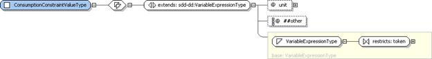
Figure 34:
ConsumptionConstraintValueType structure.
A consumption value is defined using a
variable expression. ConsumptionConstraintValueType
provides the variable expression by extending VariableExpressionType.
4.4.4.1 ConsumptionConstraintValueType
Property Summary
|
Name
|
Type
|
*
|
Description
|
|
|
[extends]
VariableExpressionType
|
|
See
the VariableExpressionType section for additional properties [4.6.1].
|
|
unit
|
xsd:string
|
0..1
|
Unit
of measure used to interpret the consumption value.
|
|
|
xsd:anyAttribute
|
0..*
|
|
4.4.4.2 ConsumptionConstraintValueType
Property Usage Notes
See the VariableExpressionType
section for details of the inherited attributes and elements [4.6.1].
§
unit:
Values for unit SHOULD be well-known
units of measure from International System of Units [UNIT]. A unit of measure SHOULD be specified for all
properties which are measured in any kind of unit.
Figure 35:
PropertyConstraintType structure.
PropertyConstraintType
provides the type definition of the Property
elements of RequirementResourceConstraintType
[4.7.5]. It supports definition of a required value or set
of acceptable values for a particular resource property.
4.4.5.1 PropertyConstraintType
Property Summary
|
Name
|
Type
|
*
|
Description
|
|
Description
|
DisplayTextType
|
0..1
|
A
description of the property constraint. Required if ShortDescription is
defined.
|
|
ShortDescription
|
DisplayTextType
|
0..1
|
A
short description of the property constraint.
|
|
PropertyName
|
xsd:QName
|
1
|
Name
of the constrained property.
|
|
Value
|
VariableExpressionType
|
0..1
|
Required
property value.
|
|
ListOfValues
|
PropertyValueListType
|
0..1
|
List
of required property values.
|
4.4.5.2 PropertyConstraintType
Property Usage Notes
§
Description,
ShortDescription: These elements MAY be
used to provide human-understandable information. If used, they MUST provide
a description of the property constraint on the resource.
The
Description element MUST be defined
if the ShortDescription element is
defined.
See
the DescriptionGroup section for
structure and additional usage details [4.14.1].
§
PropertyName:
The property name can be used to find the property value in the deployment
environment. This name may be specified in profiles [5.3].
§
Value:
The result of evaluating this variable expression represents the required value
of the named resource property.
See the VariableExpressionType
section for structure and additional usage details [4.6.1].
§
ListOfValues:
A list of required values can be defined in place of a single required value.
See the PropertyValueListType
section for structure and additional usage details [4.4.6].
Figure 36: PropertyValueListType
structure.
A property value list is expressed as one or
more strings representing valid values for the property.
4.4.6.1 PropertyValueListType
Property Summary
|
Name
|
Type
|
*
|
Description
|
|
Value
|
VariableExpressionType
|
1..*
|
A
property value.
|
|
match
|
PropertyMatchType
|
0..1
|
Determines
whether the actual property value must match any or all of the listed values.
**default
value=“any”
|
|
|
xsd:anyAttribute
|
0..*
|
|
4.4.6.2 PropertyValueListType
Property Usage Notes
§
Value:
The result of this variable expression represents one possible required value
of the named resource property.
See the VariableExpressionType
section for structure and additional usage details [4.6.1].
§
match:
The value or values of the property found in the deployment environment are
compared to the value or values listed in the property constraint. PropertyMatchType defines two enumerated
values: any and all. When match is set to
any, the property constraint is
considered met when any one of the found property values matches any one of the
declared property values. When match
is set to all, the constraint is
considered met when all of the declared property values match values found for
the property.
Figure 37: VersionConstraintType
structure.
VersionConstraintType
provides the type definition of the VersionConstraint
elements of RequirementResourceConstraintType
[4.7.5]. A VersionConstraint
can define a set of individual versions or ranges of versions that are
supported and a similar set that are certified.
4.4.7.1 VersionConstraintType
Property Summary
|
Name
|
Type
|
*
|
Description
|
|
Description
|
DisplayTextType
|
0..1
|
A
description of the version constraint. Required if ShortDescription is
defined.
|
|
ShortDescription
|
DisplayTextType
|
0..1
|
A
short description of the version constraint.
|
|
Supported
|
VersionConstraintValueType
|
1
|
A
supported version or set of versions.
|
|
Certified
|
VersionConstraintValueType
|
0..1
|
A
subset of the supported versions that are certified as tested.
|
4.4.7.2 VersionConstraintType
Property Usage Notes
§
Description,
ShortDescription: These elements MAY be
used to provide human-understandable information. If used, they MUST provide
a description of the version constraint on the resource.
The
Description element MUST be defined
if the ShortDescription element is
defined.
See
the DescriptionGroup section for
structure and additional usage details [4.14.1].
§
Supported:
If the resource version is in the Supported
set, it meets the requirements.
See the VersionConstraintValueType
section for structure and additional usage details [4.4.8].
§
Certified:
In some cases the set of required versions may be different from the set of
versions that are certified by the manufacturer as thoroughly tested.
See the VersionConstraintValueType
section for structure and additional usage details [4.4.8].
Figure 38:
VersionConstraintValueType structure.
A version constraint can be specified using
any number of individual version values in combination with any number of
version ranges.
4.4.8.1 VersionConstraintValueType
Property Summary
|
Name
|
Type
|
*
|
Description
|
|
Value
|
VersionValueType
|
0..*
|
A
version value with associated fixes specified.
|
|
Range
|
VersionRangeType
|
0..*
|
A
range of version values with associated fixes specified for each range.
|
4.4.8.2 VersionConstraintValueType
Property Usage Notes
§
Value:
Discrete version values can be defined when the set of required versions
includes versions that do not fall within a range. There is no assumption by
this specification that version values are numerically comparable. The method
of comparing version values may be resource-specific.
See the VersionValueType
section for structure and additional usage details [4.4.9].
§
Range:
See the VersionRangeType section for
structure and additional usage details [4.4.10].
Figure 39: VersionValueType
structure.
A version value includes a version and a
list of required fixes associated with that version.
4.4.9.1 VersionValueType
Property Summary
|
Name
|
Type
|
*
|
Description
|
|
Version
|
VersionType
|
1
|
An
allowable version value.
|
|
FixName
|
xsd:string
|
0..*
|
The
name of a fix.
|
4.4.9.2 VersionValueType
Property Usage Notes
§
Version:
A string containing a single, exact version value. This is compared with the
version value of specific resource instances. Only equal values satisfy this
part of the constraint.
See the VersionType
section for structure and additional usage details [3.10].
§
FixName:
Any number of FixName elements can be
defined, identifying fixes that must be discovered to be applied for the
version constraint to be considered met.
Figure 40: VersionRangeType
structure.
A VersionRange
is specified with a minimum and maximum version value and a list of required
fixes associated with that range. The method of comparing version strings in a
version range is resource-specific.
4.4.10.1 VersionRangeType
Property Summary
|
Name
|
Type
|
*
|
Description
|
|
MinVersion
|
VersionType
|
0..1
|
The
least allowable version value.
|
|
MaxVersion
|
MaxVersionType
|
0..1
|
The
greatest allowable version value.
|
|
FixName
|
xsd:string
|
0..*
|
The
name of a fix.
|
4.4.10.2 VersionRangeType
Property Usage Notes
§
MinVersion:
This is the lower bound of a version range. If MinVersion is defined but MaxVersion
is not, there is no upper bound. A version that is equal to MinVersion is within the defined range.
See the VersionType
section for structure and additional usage details [3.10].
§
MaxVersion:
This is the upper bound of a version range. If MaxVersion is defined but MinVersion
is not, there is no lower bound. A version that is equal to MaxVersion may be within the defined
range depending on the value specified for the inclusive attribute.
See the MaxVersionType
section for structure and additional usage details [4.4.11].
§
FixName:
Any number of FixNames can be defined
identifying fixes that must be found to be applied for the version constraint
is to be considered satisfied. This is true for all versions within the defined
range.
When
FixName is defined, either a MinVersion or a MaxVersion element MUST also be defined.
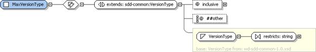
Figure 41: MaxVersionType
structure.
A maximum version can be inclusive or
exclusive.
4.4.11.1 MaxVersionType
Property Summary
|
Name
|
Type
|
*
|
Description
|
|
|
[extends]
VersionType
|
|
See
the VersionType section for additional properties [3.10].
|
|
inclusive
|
xsd:boolean
|
0..1
|
Indicates
whether the max version value is included in the supported range of versions.
**default
value=“false”
|
|
|
xsd:any
|
0..*
|
|
4.4.11.2 MaxVersionType
Property Usage Notes
See the VersionType
section for details of the inherited attributes and elements [3.10].
§
inclusive:
The inclusive attribute allows the
SDD author to choose the semantics of maximum version. Supported ranges are
often everything equal to or greater than the minimum version and up to, but
not including, the maximum version. Sometimes it is more convenient for the
range to include the maximum version.
Figure 42:
UniquenessConstraintType structure.
A UniquenessConstraint
is used to indicate when two resources defined in topology MUST or MUST NOT
resolve to the same resource instance during a particular deployment. A UniquenessConstraint indicates that the
two resources MUST NOT be the same when it is defined in a ResourceConstraint element with testValue=“true”. A UniquenessConstraint indicates that the
two resources MUST be the same when defined in a ResourceConstraint with testValue=“false”.
When no UniquenessConstraint
is in scope for a particular pair of resources, the two resources MAY resolve
to the same resource when their identifying characteristics are the same and
when all in-scope constraints on both resources are satisfied.
The first of the pair of resources is
identified in the resourceRef
attribute of the ResourceConstraint
element that defines the UniquenessConstraint.
The second of the pair is identified in the distinctResourceRef
attribute of the UniquenessConstraint.
4.4.12.1 UniquenessConstraintType
Property Summary
|
Name
|
Type
|
*
|
Description
|
|
Description
|
DisplayTextType
|
0..1
|
A
description of the uniqueness constraint, for example what must or must not
be unique and why.
|
|
ShortDescription
|
DisplayTextType
|
0..1
|
A
short description of the uniqueness constraint.
|
|
distinctResourceRef
|
xsd:IDREF
|
1
|
One
of the pair of resources referred to by the constraint.
|
4.4.12.2 UniquenessConstraintType
Property Usage Notes
§
Description,
ShortDescription: These elements MAY be
used to provide human-understandable information. If used, they MUST provide
a description of the uniqueness constraint on the resource.
The
Description element MUST be defined
if the ShortDescription element is
defined.
See
the DescriptionGroup section for
structure and additional usage details [4.14.1].
§
distinctResourceRef:
The second resource in the pair of resources.
The
value MUST reference the id of a
resource element in Topology.
Figure 43:
RelationshipConstraintType structure.
A RelationshipConstraint
identifies a particular relationship between two resources that is constrained
in some way by the SDD. The value of the testValue
attribute of the ResourceConstraint
that contains the RelationshipConstraint
determines whether the constraint MUST be satisfied or MUST NOT be satisfied.
The first resource of the pair is defined by
the resourceRef attribute of the ResourceConstraint containing the RelationshipConstraint.
4.4.13.1 RelationshipConstraintType
Property Summary
|
Name
|
Type
|
*
|
Description
|
|
Description
|
DisplayTextType
|
0..1
|
A
description of the relationship and its purpose in the overall solution.
|
|
ShortDescription
|
DisplayTextType
|
0..1
|
A
short description of the relationship.
|
|
Property
|
PropertyType
|
0..*
|
A
property constraint that further constrains the relationship.
|
|
relatedResourceRef
|
xsd:IDREF
|
0..1
|
The
second resource in the relationship.
|
|
type
|
xsd:QName
|
1
|
The
type of the relationship.
|
|
|
xsd:anyAttribute
|
0..*
|
|
4.4.13.2 RelationshipConstraintType
Property Usage Notes
§
Description,
ShortDescription: These elements MAY be
used to provide human-understandable information. If used, they MUST provide
a description of the relationship constraint on the resource.
The
Description element MUST be defined
if the ShortDescription element is
defined.
See
the DescriptionGroup section for
structure and additional usage details [4.14.1].
§
Property:
This element MAY be used to provide additional constraints on the relationship.
For example, a connectivity relationship
might specify additional information such as the specific protocol used (for
instance, TCP/IP) and/or particular characteristics of a protocol (for
instance, port number).
See the PropertyType
section for structure and additional usage details [4.2.3].
§
relatedResourceRef:
Naming the second resource is optional. When it is not named, the relationship
constraint is satisfied if the first resource has the defined relationship with
any other resource.
When
it is named, the value MUST reference the id
of a resource element in Topology.
§
type:
Values for relationship type are not defined by the SDD specification.
Conditions are expressed on characteristics
of resources in the deployment environment. Conditions are used to indicate
when particular elements of the SDD are applicable, or when they should be
ignored. Conditions are not requirements. Failure to satisfy a condition does
not indicate a failure; it simply means the conditioned element should be
ignored. Conditions are used to:
§
determine if a content element is applicable
§
choose from among values for a variable
§
determine when a feature is applicable
§
determine when a particular result is applicable
§
determine if a particular completion action is
necessary.
Because conditions are always based on the
characteristics of resources, they are expressed using resource constraints.
Figure 44: ConditionType
structure.
ConditionType
allows expression of the particular resource characteristics that must be true
for the condition to be considered met. These are resource characteristics that
may vary from one particular deployment to another.
For example, one deployment using the SDD
might use one version of an application server and a different deployment might
use a different version. The differences in the version might be great enough
to:
·
select among content elements.
For example, one content element has an
artifact for a Web application that works in a particular version and a
different content element has an artifact for a later version of the same Web
application.
·
select among variable values.
For example, the default installation path
on one operating system may be different from the default install path on
another operating system.
·
select among completion actions.
For example, a reboot may be required when
deploying on one operating system but not another.
4.5.1.1 ConditionType
Property Summary
|
Name
|
Type
|
*
|
Description
|
|
DisplayName
|
DisplayTextType
|
0..1
|
Name
of the condition.
|
|
Description
|
DisplayTextType
|
0..1
|
Description
of the condition.
|
|
ShortDescription
|
DisplayTextType
|
0..1
|
Short
description of the condition.
|
|
Alternative
|
AlternativeConditionalType
|
0..*
|
An
alternative set of resource constraints.
|
|
ResourceConstraint
|
ConditionalResourceConstraintType
|
0..*
|
A
set of constraints on one resource.
|
|
|
xsd:any
|
0..*
|
|
|
operation
|
OperationListType
|
0..1
|
The
condition applies only when processing the artifact associated with this
operation.
|
|
|
xsd:anyAttribute
|
0..*
|
|
4.5.1.2 ConditionType
Property Usage Notes
§
DisplayName:
This element MAY be
used to provide human-understandable information. If used, it MUST provide
a label for the condition.
See the DisplayElementGroup
section for structure and additional usage details [4.14.2].
§
Description,
ShortDescription: These elements MAY be
used to provide human-understandable information. If used, they MUST provide
a description of the condition.
The
Description element MUST be defined
if the ShortDescription element is
defined.
See
the DisplayElementGroup section for
structure and additional usage details [4.14.2].
§
Alternative:
When a condition can be satisfied in multiple ways, two or more Alternative elements are defined.
As a convenience for tooling that produces
SDDs, it is also possible to define a single Alternative. This is semantically identical to directly defining ResourceConstraints.
To meet a condition, at least one of the
specified Alternatives must be
satisfied.
See the AlternativeConditionalType
section for structure and additional usage details [4.5.2].
§
ResourceConstraint:
When a condition can be satisfied in only one way, constraints MAY be defined
directly under Condition or in a
single Alternative element.
Constraints are defined using a sequence of ResourceConstraints. Every constraint in
the sequence must be met for the condition to be met.
See
the ConditionalResourceConstraintType
section for structure and additional usage details [4.5.3].
§
operation:
In a singleton atomic content element, a condition MAY be associated with
application of one or more artifacts. The association is made by setting the operation attribute to the operations
associated with those artifacts.
Conditions
defined for CompositeInstallable and
for atomic content elements defined within a CompositeInstallable SHOULD NOT define operation. If the operation
is defined for a CompositeInstallable
Condition, it MUST be set to the operation defined in the CompositeInstallable’s operation attribute. If operation is defined for an atomic
content element’s Condition, it MUST
be set to the operation associated with the single artifact defined by the
atomic content element.
When operation
is not specified, the condition applies to the processing of all artifacts.
See the OperationListType
section for operation enumerations
and their meaning [4.3.6].
Figure 45:
AlternativeConditionalType structure.
When a condition can be met in more than one
way, alternative sets of conditional resource constraints can be defined. AlternativeConditionalType provides the
type definition for these elements.
4.5.2.1 AlternativeConditionalType
Property Summary
|
Name
|
Type
|
*
|
Description
|
|
DisplayName
|
DisplayTextType
|
0..1
|
Name
of the alternative.
|
|
Description
|
DisplayTextType
|
0..1
|
Description
for the alternative.
|
|
ShortDescription
|
DisplayTextType
|
0..1
|
Short
description of the alternative.
|
|
ResourceConstraint
|
ConditionalResourceConstraintType
|
1..*
|
A set of constraints on one resource.
|
|
|
xsd:any
|
0..*
|
|
|
id
|
xsd:IDREF
|
1
|
Identifier
for the alternative that is unique within the deployment descriptor.
|
|
|
xsd:anyAttribute
|
0..*
|
|
4.5.2.2 AlternativeConditionalType
Property Usage Notes
§
DisplayName:
This element MAY be
used to provide human-understandable information. If used, it MUST provide
a label for the alternative condition.
See the DisplayElementGroup
section for structure and additional usage details [4.14.2].
§
Description,
ShortDescription: These elements MAY be
used to provide human-understandable information. If used, they MUST provide
a description of the alternative condition.
The
Description element MUST be defined
if the ShortDescription element is
defined.
See
the DisplayElementGroup section for
structure and additional usage details [4.14.2].
§
ResourceConstraint:
All constraints defined in the individual Alternative
MUST be met for the Alternative
condition to evaluate to true.
See the ConditionalResourceConstraintType
section for structure and additional usage details [4.5.3].
§
id:
The id attribute may be useful to
software that processes the SDD, for example, for use in creating log and trace
messages.
Figure 46:
ConditionalResourceConstraintType structure.
ConditionalResourceConstraintType
provides the type definitions for the ResourceConstraint
elements used in conditions. These constraints do not represent requirements
for deployment. They identify the resource characteristics associated with a
condition. Name, version, property and the existence or absence of the resource
can be specified with a resource constraint used in a condition.
4.5.3.1 ConditionalResourceConstraintType
Property Summary
|
Name
|
Type
|
*
|
Description
|
|
DisplayName
|
DisplayTextType
|
0..1
|
Name
of the resource constraint.
|
|
Description
|
DisplayTextType
|
0..1
|
Description
for the resource constraint.
|
|
ShortDescription
|
DisplayTextType
|
0..1
|
Short
description of the resource constraint.
|
|
Name
|
VariableExpressionType
|
0..1
|
Name
of the resource constraint.
|
|
VersionConstraint
|
VersionConstraintValueType
|
0..1
|
A
resource version set.
|
|
PropertyConstraint
|
ConditionalPropertyConstraintType
|
0..*
|
A
resource property name and required value.
|
|
UniquenessConstraint
|
UniquenessConstraintType
|
0..*
|
A required mapping of two resources in the
topology to unique instances in the deployment environment.
|
|
RelationshipConstraint
|
RelationshipConstraintType
|
0..*
|
A
required relationship between the resource identified in the resourceRef and
another resource in the topology.
|
|
|
xsd:any
|
0..*
|
|
|
id
|
xsd:ID
|
1
|
Identifier
for the resource constraint that is unique within the deployment descriptor.
|
|
resourceRef
|
xsd:IDREF
|
1
|
The
resource to which the conditions apply.
|
|
testValue
|
xsd:boolean
|
0..1
|
The
result of evaluating the contained constraints, which will result in the ResourceConstraint
being met.
**default
value=“true”
|
|
|
xsd:anyAttribute
|
0..*
|
|
4.5.3.2 ConditionalResourceConstraintType
Property Usage Notes
§
DisplayName:
This element MAY be
used to provide human-understandable information. If used, it MUST provide
a label for the resource constraint.
See the DisplayElementGroup
section for structure and additional usage details [4.14.2].
§
Description,
ShortDescription: These elements MAY be
used to provide human-understandable information. If used, they MUST provide
a description of the resource constraint.
The
Description element MUST be defined
if the ShortDescription element is
defined.
See
the DisplayElementGroup section for
structure and additional usage details [4.14.2].
§
Name:
The name of the resource identified by resourceRef.
If the resource name is defined in topology it SHOULD NOT be defined here. If
it is defined in both places, the one defined in the condition is used when
evaluating the condition.
See the VariableExpressionType
section for structure and additional usage details [4.6.1].
§
VersionConstraint:
The actual version of the resource MUST be one of the set of versions defined
here for the version condition to be considered met.
See the VersionConstraintValueType
section for structure and additional usage details [4.4.8].
§
PropertyConstraint:
The actual value of the property MUST match the value defined here for the
condition to be considered met.
See the ConditionalPropertyConstraintType
section for structure and additional usage details [4.5.4].
§
UniquenessConstraint:
UniquenessConstraint elements are
used in ResourceConstraints to indicate
when two resources defined in topology MUST or MUST NOT resolve to the same
resource instance during a particular deployment.
See the UniquenessConstraintType
section for structure and additional usage details [4.4.12].
§
RelationshipConstraint:
RelationshipConstraint elements are
used in ResourceConstraints to indicate
a constraint on a particular relationship between resources.
See the RelationshipConstraintType
section for structure and additional usage details [4.4.13].
§
id:
The id attribute may be useful to
software that processes the SDD, for example, for use in creating log and trace
messages.
§
resourceRef:
The version and property constraints defined here all apply to the one resource
specification in topology identified by this attribute.
The
value MUST reference the id of that
resource element in Topology.
§
testValue:
When the result of evaluating Name
and all of the constraints defined in the ResourceConstraint
matches the value of testValue, the ResourceConstraint is considered met.
When
no name, version or property constraints are defined, and testValue is “true”, the constraint is met if the resource exists
as defined in topology.
When
no name, version or property constraints are defined, and testValue is “false”, the constraint is met if the resource, as
defined in topology, does not exist.
Figure 47:
ConditionalPropertyConstraintType structure.
ConditionalPropertyConstraintType
provides the type definition for a PropertyConstraint
included within Alternatives specified
in Condition elements. The ConditionalPropertyConstraintType is
very similar to the PropertyConstraintType;
the only difference is that the Value
element defined in the ConditionalPropertyConstraintType
is of type xsd:string which is less restrictive than the Value element defined in the PropertyConstraintType which is of VariableExpressionType.
4.5.4.1 ConditionalPropertyConstraintType
Property Summary
|
Name
|
Type
|
*
|
Description
|
|
Description
|
DisplayTextType
|
0..1
|
A
description of the property constraint. Required if ShortDescription is
defined.
|
|
ShortDescription
|
DisplayTextType
|
0..1
|
A
short description of the property constraint.
|
|
PropertyName
|
xsd:QName
|
1
|
Name
of the constrained property.
|
|
Value
|
xsd:string
|
0..1
|
Required
property value.
|
|
ListOfValues
|
PropertyValueListType
|
0..1
|
List
of required property values.
|
4.5.4.2 ConditionalPropertyConstraintType
Property Usage Notes
§
Description,
ShortDescription: These elements MAY be
used to provide human-understandable information. If used, they MUST provide
a description of the PropertyConstraint
element.
The
Description element MUST be defined
if the ShortDescription element is
defined.
See
the DescriptionGroup section for
structure and additional usage details [4.14.1].
§
PropertyName:
The property name can be used to find the property value in the deployment
environment. The name may be defined in a profile [5.3].
§
Value:
In a condition, the value used in a property constraint is a string rather than
a variable expression.
§
ListOfValues:
A list of required values can be defined in place of a single required value.
See
the PropertyValueListType section for
structure and additional usage details [4.4.6].
Variables provide a means to associate user
inputs, resource property values, fixed strings and values derived from these
with input arguments for artifacts and with constraints on resources.
Figure 48:
VariableExpressionType structure.
Variable expressions are used in many places
in the SDD. They allow the value of a variable to be used as all, or part of, the
value of some other SDD element. A variable expression is a string that can
include a reference to a variable. The string is evaluated by replacing all
references to variables with the value of the variable. A variable reference is
a variable id placed inside parentheses preceded by a dollar sign.
For example, the variable expression
“C:\Program Files\$(InstallDirectory)” resolves to “C:\Program Files\Acme
Software Product” if the value of the variable with the id “InstallDirectory”
has the value “Acme Software Product”.
The value of a variable that is replaced
into a variable expression can itself have a variable reference. This reference
is resolved before using the value. This nesting of variable expressions is
unlimited. Any number of variable references can be used in a variable
expression. If a variable expression string does not contain a variable
reference, it is used as is.
A variable is considered defined if it has a
value provided, even if that value is the empty string. A variable expression
is considered valid if it contains no variable references, or if all contained
variable references are defined.
Specifically, a ResourceProperty
variable is undefined when the resource does not participate in the particular
deployment or when the specified property has no value. A Parameter
variable is undefined when it has no default value and has no value provided by
the deployer. A DerivedVariable that uses ConditionalExpression
elements is undefined when none of its conditions evaluates to true, or the
selected condition's value expression is not valid. A DerivedVariable
that uses an unconditioned Expression is undefined when its value expression
is undefined.
To avoid an undefined Parameter
variable, default parameter values may be used. To avoid an undefined ResourceProperty
variable, replace references to the ResourceProperty variable with
references to a DerivedVariable defined to provide a default value in
cases where the ResourceProperty is undefined. This DerivedVariable
would define one expression, conditioned on the resource, that refers to the ResourceProperty
variable and another, low priority, catch-all expression that defines the
desired “default” value. Note that the
default value in either of these cases MAY be an empty string, for example, “”. An empty string acts just like
any other defined variable value. When the provided value of a variable is an
empty string, the variable reference in a variable expression is replaced by an
empty string.
Figure 49: BaseVariableType
structure.
BaseVariableType
is the base type of the DerivedVariable
and ResourceProperty elements defined
by VariablesType [4.6.3]. It provides the id
attribute, which is used to reference the variable in a variable expression.
4.6.2.1 BaseVariableType
Property Summary
|
Name
|
Type
|
*
|
Description
|
|
Description
|
DisplayTextType
|
0..1
|
Description
of the variable.
|
|
ShortDescription
|
DisplayTextType
|
0..1
|
Short
description of the variable.
|
|
id
|
xsd:ID
|
1
|
Identifier
used for referencing the variable within the descriptor.
|
|
sensitive
|
xsd:boolean
|
0..1
|
A
“true” value indicates the variable contains sensitive data.
**default
value=“false”
|
4.6.2.2 BaseVariableType
Property Usage Notes
§
Description,
ShortDescription: These elements MAY be
used to provide human-understandable information. If used, they MUST provide
a description of the variable.
The
Description element MUST be defined
if the ShortDescription element is
defined.
See
the DescriptionGroup section for
structure and additional usage details [4.14.1].
§
id:
Variables may be referenced in deployment descriptor elements of type VariableExpression within the scope of
the variable. The scope of the variable includes the content element where
defined and all nested content elements. Variables
defined in the top level content element are also visible in Topology. The Variable is referenced by placing the variable id within parentheses preceded by a dollar sign.
For example, a variable with id value “InstallLocation” is referenced
with the string “$(InstallLocation)”.
The id
attribute may be useful to software that processes the SDD, for example, for
use in creating log and trace messages.
§
sensitive:
The sensitive attribute provides an
indication of whether the data within a variable is likely to be considered
sensitive. User name and password are examples of data that may be considered
sensitive.
For example, sensitive data typically would not be displayed in a user
interface, written to a log file, stored without protection, or in any way made
visible except to authorized users.
The default value is “false”.
Figure 50: VariablesType
structure.
There are three types of variables that can
be defined in a content element: input parameter variables, variables that take
the value of a resource property, and variables whose value is derived from a
variable expression.
A variable is in scope for a particular
deployment when the content element that defines the variable is in scope for
that deployment.
4.6.3.1 VariablesType
Property Summary
|
Name
|
Type
|
*
|
Description
|
|
Parameters
|
ParametersType
|
0..*
|
A
list of variables whose values can be supplied as input to the deployment
process.
|
|
ResourceProperty
|
ResourcePropertyType
|
0..*
|
A
variable whose value is set from the value of a resource property.
|
|
DerivedVariable
|
DerivedVariableType
|
0..*
|
A
set of expressions with optional associated conditions. The DerivedVariable’s
value is determined by evaluating the conditions and then setting the
variable value to the result of the top priority expression from the set of
expressions whose conditions evaluate to true.
|
|
|
xsd:any
|
0..*
|
|
4.6.3.2 VariablesType
Property Usage Notes
§
Parameters:
See the ParametersType section for
structure and additional usage details [4.6.4].
§
ResourceProperty:
See the ResourcePropertyType section
for structure and additional usage details [4.6.12].
§
DerivedVariable:
See the DerivedVariableType section
for structure and additional usage details [4.6.13].
Figure 51: ParametersType
structure.
Parameters are variables whose value is
expected to be received as input to the deployment process. The SDD author can
specify multiple specific types of parameters, including validation rules for
the values of the parameters.
4.6.4.1 ParametersType
Property Summary
|
Name
|
Type
|
*
|
Description
|
|
IntegerParameter
|
IntegerParameterType
|
0..*
|
An
integer input parameter.
|
|
StringParameter
|
StringParameterType
|
0..*
|
A
string input parameter.
|
|
BooleanParameter
|
BooleanParameterType
|
0..*
|
A
boolean input parameter.
|
|
URIParameter
|
URIParameterType
|
0..*
|
A
Universal Resource Identifier input parameter.
|
|
|
xsd:any
|
0..*
|
|
4.6.4.2 ParametersType
Property Usage Notes
§
IntegerParameter:
See the IntegerParameterType section
for structure and additional usage details [4.6.6].
§
StringParameter:
See the StringParameterType section
for structure and additional usage details [4.6.8].
§
BooleanParameter:
See the BooleanParameterType section
for structure and additional usage details [4.6.10].
§
URIParameter:
See the URIParameterType section for
structure and additional usage details [4.6.11].
Figure 52: BaseParameterType
structure.
BaseParameterType
provides a default value, along with other attributes used by all parameter
types. It also provides the id
attribute, which is used to reference the parameter in variable expressions.
4.6.5.1 BaseParameterType
Property Summary
|
Name
|
Type
|
*
|
Description
|
|
DisplayName
|
DisplayTextType
|
0..1
|
Name
of the parameter.
|
|
Description
|
DisplayTextType
|
0..1
|
Description
of the parameter.
|
|
ShortDescription
|
DisplayTextType
|
0..1
|
Short
description of the parameter.
|
|
id
|
xsd:ID
|
1
|
Identifier
used for referencing the variable within the descriptor.
|
|
defaultValue
|
VariableExpressionType
|
0..1
|
Default
value for the parameter.
|
|
sensitive
|
xsd:boolean
|
0..1
|
A
“true” value indicates the variable contains sensitive data.
**default
value=“false”
|
|
required
|
xsd:boolean
|
0..1
|
A
“true” value indicates that a value for the parameter must be provided.
**default
value=“true”
|
|
operation
|
OperationListType
|
0..1
|
The
parameter is used when the specified operation(s) is (are) performed.
|
4.6.5.2 BaseParameterType
Property Usage Notes
§
DisplayName:
This element MAY be
used to provide human-understandable information. If used, it MUST provide
a label for the parameter.
See the DisplayElementGroup
section for structure and additional usage details [4.14.2].
§
Description,
ShortDescription: These elements MAY be
used to provide human-understandable information. If used, they MUST provide
a description of the parameter.
These
elements may be used to assist the deployer in understanding the purpose and
expected values for the parameters.
The
Description element MUST be defined
if the ShortDescription element is
defined.
See
the DisplayElementGroup section for
structure and additional usage details [4.14.2].
§
id: Parameters
may be referenced in DeploymentDescriptor
elements of type VariableExpression
within the scope of the parameter variable. The scope of the variable includes
the content element where the variable is defined and all nested content
elements. Variables defined in the top level content element are also visible
in Topology. The Variable is referenced by placing the variable id within parentheses preceded by a dollar sign.
For example, a variable with id value “InstallLocation” is referenced
with the string “$(InstallLocation)”.
The id
attribute may be useful to software that processes the SDD, for example, for
use in creating log and trace messages.
§
defaultValue:
The defaultValue is used if no other
value is provided as input to the deployment process.
The value is interpreted based on the type
of the defining parameter.
For example, the defaultValue for a BooleanParameter
must be either “true” or “false”; the defaultValue
for a StringParameter must be a
string; etc.
See the VariableExpressionType
section for structure and additional usage details [4.6.1].
§
sensitive:
The sensitive attribute provides an
indication of whether the data within a variable is likely to be considered
sensitive. User name and password are examples of data that may be considered
sensitive.
For example, sensitive data typically would not be displayed in a user
interface, written to a log file, stored without protection, or in any way made
visible except to authorized users.
§
required:
A “true” value for required indicates
that a value for the parameter must be provided when the parameter is in scope
for a particular deployment.
In
cases where the parameter should be ignored when the value expression is not
valid for a particular deployment, set required to "false".
A “false” value for the required attribute has no effect when defaultValue is set.
§
operation:
This attribute enables unique parameters to be defined per operation. Note that
the use of a parameter for a particular operation is determined by a reference
to the parameter in a variable expression or artifact argument used when performing
that operation. The operation(s) associated with a parameter’s use can be
determined by examining its use in the SDD. The operation attribute provides a quick way to know which operation(s)
will use the parameter without having to examine the use of the parameter.
All
parameters defined within a CompositeInstallable
are associated with the single operation supported by the CompositeInstallalbe. The operation
attribute SHOULD NOT be set in this situation.
See the OperationListType
section for operation enumerations
and their meaning [4.3.6].
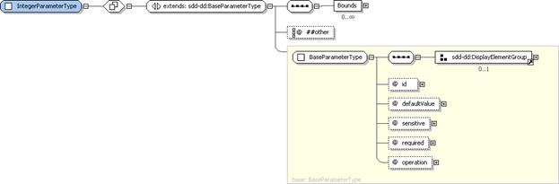
Figure 53: IntegerParameterType
structure.
IntegerParameterType
defines upper and lower bounds that can be used to validate the input received
for that parameter.
4.6.6.1 IntegerParameterType
Property Summary
|
Name
|
Type
|
*
|
Description
|
|
|
[extends]
BaseParameterType
|
|
See
the BaseParameterType section for additional properties [4.6.5].
|
|
Bounds
|
BoundaryType
|
0..*
|
Specifies
the boundaries for the value of the parameter.
|
|
|
xsd:anyAttribute
|
0..*
|
|
4.6.6.2 IntegerParameterType
Property Usage Notes
See the BaseParameterType
section for details of the inherited attributes and elements [4.6.5].
§
Bounds:
If there are restrictions on the range of values that are valid for a
parameter, those restrictions MUST be specified in Bounds.
See the BoundaryType
section for structure and additional usage details [4.6.7].
Figure 54: BoundaryType
structure.
BoundaryType
defines upper and lower bounds that can be used to validate the input received
for that parameter.
4.6.7.1 BoundaryType
Property Summary
|
Name
|
Type
|
*
|
Description
|
|
LowerBound
|
VariableExpressionType
|
0..1
|
Lowest
valid value for the parameter.
|
|
UpperBound
|
VariableExpressionType
|
0..1
|
Highest
valid value for the parameter.
|
4.6.7.2 BoundaryType
Property Usage Notes
§
LowerBound:
This variable expression MUST resolve to an integer.
If
no LowerBound is specified, no
integer value is too low.
A LowerBound
of “0” restricts the integer parameter to positive integer values.
See the VariableExpressionType
section for structure and additional usage details [4.6.1].
§
UpperBound:
This variable expression MUST resolve to an integer.
If
no UpperBound is specified, no
integer value is too high.
See the VariableExpressionType
section for structure and additional usage details [4.6.1].
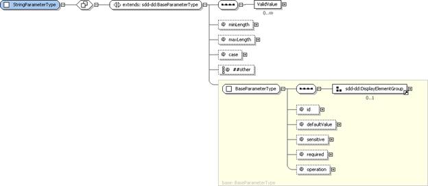
Figure 55: StringParameterType
structure.
StringParameterType
supports definition of minimum and maximum lengths that can be used to validate
the input received for the string parameter. It also supports definition of a
list of valid input values.
4.6.8.1 StringParameterType
Property Summary
|
Name
|
Type
|
*
|
Description
|
|
|
[extends]
BaseParameterType
|
|
See
the BaseParameterType section for additional properties [4.6.5].
|
|
ValidValue
|
xsd:string
|
0..*
|
A
string representing one valid value for the parameter.
|
|
minLength
|
xsd:positiveInteger
|
0..1
|
Minimum
length of the parameter value.
|
|
maxLength
|
xsd:positiveInteger
|
0..1
|
Maximum
length of the parameter value.
|
|
case
|
StringCaseType
|
0..1
|
The
case of the string–“upper”, “lower” or “mixed”.
**default
value=“mixed”
|
|
|
xsd:anyAttribute
|
0..*
|
|
4.6.8.2 StringParameterType
Property Usage Notes
See the BaseParameterType
section for details of the inherited attributes and elements [4.6.5].
§
ValidValue:
Any number of valid values for the parameter can be listed using ValidValue elements.
When
both defaultValue and one or more ValidValues are specified, defaultValue MUST match one of the ValidValues.
ValidValues should be in the correct
case as identified in the case
attribute.
§
minLength:
When no minimum length is specified, no string is too short, including an empty
string.
§
maxLength:
When no maximum length is specified, no string is too long.
§
case:
Used when the case of the string is restricted. Defaults to mixed if not defined.
See
the StringCaseType section for enumeration
values and their meaning [4.6.9].
StringCaseType
defines the enumeration values for specifying case restrictions on a string
parameter.
4.6.9.1 StringCaseType
Property Usage Notes
§
lower:
The string MUST be lower case.
§
upper:
The string MUST be upper case.
§
mixed:
The string SHOULD be mixed case.
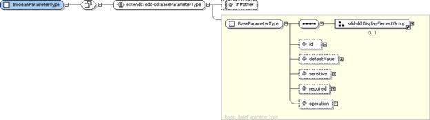
Figure 56: BooleanParameterType
structure.
BooleanParameterType
extends BaseParameterType without
adding any additional attributes or elements. When the defaultValue attribute is defined for a boolean parameter, its
value MUST be either “true” or “false”. See the BaseParameterType section for details of the inherited attributes
and elements [4.6.5].
4.6.10.1 BooleanParameterType
Property Summary
|
Name
|
Type
|
*
|
Description
|
|
|
[extends]
BaseParameterType
|
|
See
the BaseParameterType section for additional properties [4.6.5].
|
|
|
xsd:anyAttribute
|
0..*
|
|
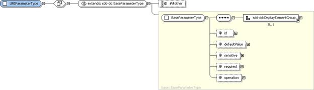
Figure 57: URIParameterType
structure.
When the default value attribute is
specified for a URI parameter, its value MUST be a valid Uniform Resource
Identifier. See the BaseParameterType
section for details of the inherited attributes and elements [4.6.5].
4.6.11.1 URIParameterType
Property Summary
|
Name
|
Type
|
*
|
Description
|
|
|
[extends]
BaseParameterType
|
|
See
the BaseParameterType section for additional properties [4.6.5].
|
|
|
xsd:anyAttribute
|
0..*
|
|
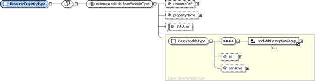
Figure 58: ResourcePropertyType
structure.
ResourcePropertyType
provides the type definition for the ResourceProperty
element of VariablesType [4.6.3]. ResourceProperty
is a variable whose value is set from the property of a specific instance of a
resource during a particular solution deployment. All content elements can
define ResourceProperty elements.
4.6.12.1 ResourcePropertyType
Property Summary
|
Name
|
Type
|
*
|
Description
|
|
|
[extends]
BaseVariableType
|
|
See
the BaseVariableType section for additional properties [4.6.2].
|
|
resourceRef
|
xsd:IDREF
|
1
|
The
resource in Topology that owns the property.
|
|
propertyName
|
xsd:QName
|
1
|
Name
of the property whose value provides the variable’s values.
|
|
|
xsd:anyAttribute
|
0..*
|
|
4.6.12.2 ResourcePropertyType
Property Usage Notes
See the BaseVariableType
section for details of the inherited attributes and elements [4.6.2].
§
resourceRef:
The resourceRef attribute MUST identify
the resource in Topology that owns
the property and will provide the value for ResourceProperty.
§
propertyName:
The propertyName attribute identifies
the name of the resource property whose value is to be used as the value of ResourceProperty.
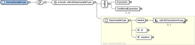
Figure 59: DerivedVariableType
structure.
A DerivedVariable
defines a series of expressions with optional conditions. The value of the
variable is determined by evaluating the boolean conditions and then setting
the variable to the result of the top priority expression from the set of
expressions whose conditions evaluate to true. This restriction does not apply
to variables of the same name in different descriptors. The SDD author MUST
create DerivedVariables in a way that
makes the selection of the expression unambiguous.
4.6.13.1 DerivedVariableType
Property Summary
|
Name
|
Type
|
*
|
Description
|
|
|
[extends]
BaseVariableType
|
|
See
the BaseVariableType section for additional properties [4.6.2].
|
|
Expression
|
VariableExpressionType
|
1
|
An
expression whose results become the value of the variable.
|
|
ConditionalExpression
|
ConditionalDerivedVariableExpressionType
|
1..*
|
An
expression and an associated condition.
|
4.6.13.2 DerivedVariableType
Property Usage Notes
See the BaseVariableType
section for details of the inherited attributes and elements [4.6.2].
§
Expression:
When the DerivedVariable is used to
define one variable whose value is not conditional, the SDD author can include
one variable expression defined in one Expression
element.
See the VariableExpressionType
section for structure and additional usage details [4.6.1].
§
ConditionalExpression:
When the variable will take one of a number of possible values depending on the
characteristics of the resources that participate in the particular deployment,
then one ConditionalExpression
element is defined for each value-condition pair.
See the ConditionalDerivedVariableExpressionType
section for structure and additional usage details [4.6.14].
Figure 60:
ConditionalDerivedVariableExpressionType structure.
ConditionalDerivedVariableExpressionType
is the type of the ConditionalExpression
elements in derived variables. These elements associate a condition with a
variable expression.
4.6.14.1 ConditionalDerivedVariableExpressionType
Property Summary
|
Name
|
Type
|
*
|
Description
|
|
Condition
|
ConditionType
|
1
|
A
set of resource characteristics that are evaluated to determine if the
associated expression is a candidate for determining the value of the derived
variable.
|
|
Expression
|
VariableExpressionType
|
1
|
Evaluation
of this expression produces a candidate value for the derived variable.
|
|
priority
|
xsd:positiveInteger
|
0..1
|
A
priority used as a tie-breaker when multiple expressions are available to
determine the value of the variable.
**default
value=“1”
|
4.6.14.2 ConditionalDerivedVariableExpressionType
Property Usage Notes
§
Condition:
Selection of conditioned expressions is based on the characteristics of one or
more resources that participate in a particular solution deployment. These characteristics
are defined in the Condition element.
See the ConditionType
section for structure and additional usage details [4.5.1].
§
Expression:
The Expression element contains the
expressions that evaluate to a potential value of the DerivedVariable. Only one expression will be selected for use in a
particular solution deployment.
See the VariableExpressionType
section for structure and additional usage details [4.6.1].
§
priority:
When multiple conditions evaluate to true for a particular deployment, the expression
chosen is determined by the priority
value. A higher priority is indicated by a lower value. “1” is the highest
priority.
Requirements
are defined by content elements. A Requirement
consists of resource constraints
that the SDD author states MUST be met prior to successful deployment or use of
the software described by the SDD package. Each Requirement definition lists one or more deployment lifecycle
operations to which the Requirement
applies. When the Requirement is
specified in an atomic content element, the operation associates the Requirement with artifacts within the
atomic content element. (See the OperationType
section for the mapping between operations and artifacts [4.3.7]. Note that the use
operation indicates that the Requirement
is associated with running of the software after deployment and not with
content element artifacts.) When the Requirement
is specified in a CompositeUnit or CompositeInstallable, the operation value MUST either be use or be the same top level operation as defined in the CompositeInstallable element. When the
Requirement is specified for a ReferencedPackage,
the operation associates the Requirement with a top level operation within the referenced SDD.
All Requirements
specified for content elements that are in scope for a particular deployment
MUST be met.
When a Requirement
can be satisfied in more than one way, Alternatives
can be defined within a Requirement.
A Requirement is considered met when
any one of the Alternatives is
satisfied.

Figure 61: RequirementsType
structure.
RequirementsType
provides the type definition for Requirements
in InstallableUnit and LocalizationUnit elements. It defines a
list of Requirement elements.
4.7.1.1 RequirementsType
Property Summary
|
Name
|
Type
|
*
|
Description
|
|
Requirement
|
RequirementType
|
1..*
|
A
requirement that must be met prior to processing the defining content
element’s artifacts.
|
4.7.1.2 RequirementsType
Property Usage Notes
§
Requirement: The Requirements element contains a sequence of Requirement elements. The Requirement
elements define requirements that MUST be met prior to successful processing of
the content element’s artifacts.
See the RequirementType
section for structure and additional usage details [4.7.2].
Figure 62: RequirementType
structure.
A Requirement
either directly defines a single set of resource constraints that MUST be met
or defines one or more alternative sets of resource constraints, only one of
which MUST be met.
When multiple Requirement elements are declared for the same operation, all MUST
be met prior to processing the associated artifact.
The association is made between a
requirement and an artifact via the operation
attribute.
4.7.2.1 RequirementType
Property Summary
|
Name
|
Type
|
*
|
Description
|
|
DisplayName
|
DisplayTextType
|
0..1
|
Name
of the requirement.
|
|
Description
|
DisplayTextType
|
0..1
|
Description
of the requirement.
|
|
ShortDescription
|
DisplayTextType
|
0..1
|
Short
description of the requirement.
|
|
Alternative
|
AlternativeRequirementType
|
0..*
|
An
alternative that can satisfy the requirement.
|
|
ResourceConstraint
|
RequirementResourceConstraintType
|
0..*
|
A
set of constraints on one resource.
|
|
Dependency
|
InternalDependencyType
|
0..*
|
A
dependency on another content element.
|
|
|
xsd:any
|
0..*
|
|
|
id
|
xsd:ID
|
1
|
Identifier
for requirement scoped to the deployment descriptor.
|
|
operation
|
OperationListType
|
1
|
Requirement
must be met before this operation is performed.
|
|
|
xsd:anyAttribute
|
0..*
|
|
4.7.2.2 RequirementType
Property Usage Notes
§
DisplayName:
This element MAY be
used to provide human-understandable information. If used, it MUST provide
a label for the requirement.
See the DisplayElementGroup
section for structure and additional usage details [4.14.2].
§
Description,
ShortDescription: These elements MAY be
used to provide human-understandable information. If used, they MUST provide
a description of the requirement.
The
Description element MUST be defined
if the ShortDescription element is
defined.
See
the DisplayElementGroup section for
structure and additional usage details [4.14.2].
§
Alternative:
Alternative elements are used when a requirement can be satisfied in multiple
ways.
As a convenience for tooling that produces
SDDs, it is also possible to define a single Alternative. This is semantically identical to directly defining ResourceConstraints under Requirements.
To satisfy a requirement, at least one of
the specified alternatives MUST be satisfied.
See the AlternativeRequirementType
section for structure and additional usage details [4.7.3].
§
ResourceConstraint:
When a requirement can be satisfied in only one way, constraints MAY be defined
directly under Requirement or in a
single Alternative element.
Constraints are defined using a sequence of ResourceConstraints. Every constraint in
the sequence MUST be met for the requirement to be met.
See the RequirementResourceConstraintType
section for structure and additional usage details [4.7.5].
§
Dependency:
When one content element must be processed before another for any reason, a pre-req type Dependency MUST be defined. Reasons for a pre-requisite dependency
include the use of an output variable from one artifact as an argument to
another; the deployment of a resource before it is configured; and the
configuration of a resource before deployment of another resource that depends
on it.
See the InternalDependencyType
section for structure and additional usage details [4.7.6].
§
id:
The id attribute may be useful to
software that processes the SDD, for example, for use in creating log and trace
messages.
§
operation:
A Requirement is associated with application
of one or more operations by setting its operation
attribute value to one of the enumerated values defined in OperationListType [4.3.6].
If the Requirement
is not a pre-requisite for application of an operation, but rather is required before
the resulting resources are considered usable, then the value SHOULD be set to use. (Note that a completion action may
also be required before a resulting resource is considered usable. See the CompletionType section [4.3.14].)
The value of operation for a Requirement
defined in an atomic content element MUST be set either to use or to an operation
that is associated with an artifact element defined in the content element’s Artifacts. The operation value(s) associate the Requirement with one or more artifact(s).
When the Requirement
is specified in a CompositeUnit or CompositeInstallable, the operation value MUST be set either to use or be the same top level operation as defined in the CompositeInstallable element.
There is no default value for operation. The SDD author must define it
explicitly.
See the OperationType
section for enumeration values and their meaning [4.3.7].
Figure 63:
AlternativeRequirementType structure.
AlternativeRequirementType
provides the type definition for Alternative
elements used within requirements to define alternative sets of resource
constraints that will satisfy the requirement.
4.7.3.1 AlternativeRequirementType
Property Summary
|
Name
|
Type
|
*
|
Description
|
|
DisplayName
|
DisplayTextType
|
0..1
|
Name
of the alternative.
|
|
Description
|
DisplayTextType
|
0..1
|
Description
of the alternative.
|
|
ShortDescription
|
DisplayTextType
|
0..1
|
Short
description of the alternative.
|
|
ResourceConstraint
|
RequirementResourceConstraintType
|
1..*
|
A
set of requirements on one resource.
|
|
Dependency
|
InternalDependencyType
|
0..*
|
A
dependency on another content element.
|
|
|
xsd:any
|
0..*
|
|
|
id
|
xsd:ID
|
1
|
Identifier
for the alternative scoped to the deployment descriptor.
|
|
priority
|
xsd:positiveInteger
|
0..1
|
Assists
in determining alternative selected when multiple alternatives evaluate to
true.
**default
value=“1”
|
|
|
xsd:anyAttribute
|
0..*
|
|
4.7.3.2 AlternativeRequirementType
Property Usage Notes
§
DisplayName:
This element MAY be
used to provide human-understandable information. If used, it MUST provide
a label for the alternative requirement.
See the DisplayElementGroup
section for structure and additional usage details [4.14.2].
§
Description,
ShortDescription: These elements MAY be
used to provide human-understandable information. If used, they MUST provide
a description of the alternative requirement.
The
Description element MUST be defined
if the ShortDescription element is
defined.
See
the DisplayElementGroup section for
structure and additional usage details [4.14.2].
§
ResourceConstraint:
Every ResourceConstraint defined in a
single Alternative MUST be met for
the alternative requirement to be considered satisfied.
See
the RequirementResourceConstraintType
section for structure and additional usage details [4.7.5].
§
Dependency:
When one content element must be processed before another for any reason, a pre-req type Dependency MUST be defined. Reasons for a pre-requisite dependency
include the use of an output variable from one artifact as an argument to
another; the deployment of a resource before it is configured; and the
configuration of a resource before deployment of another resource that depends
on it.
See the InternalDependencyType
section for structure and additional usage details [4.7.6].
§
id:
The id attribute may be useful to
software that processes the SDD, for example, for use in creating log and trace
messages.
§
priority:
If there are multiple satisfied alternatives during a particular solution
deployment, one of the alternatives must be selected. The priority attribute communicates the SDD author’s prioritization of
the alternatives. A lower number represents a higher priority with “1”
representing the highest priority. Other inputs may also be used to select an
alternative. The criteria for making this selection are outside of the scope of
the SDD.
Figure 64:
ResourceConstraintGroup structure.
The elements of ResourceConstraintGroup are used when defining content element
requirements on resources. The ResourceConstraint
element is used to group one or more constraints on a single resource.
4.7.4.1 ResourceConstraintGroup
Property Summary
|
Name
|
Type
|
*
|
Description
|
|
CapacityConstraint
|
CapacityConstraintType
|
0..1
|
A
bound on a quantifiable property of a resource.
|
|
ConsumptionConstraint
|
ConsumptionConstraintType
|
0..1
|
A
required quantity of a property of a resource in any state.
|
|
PropertyConstraint
|
PropertyConstraintType
|
0..1
|
A
required value or set of values of a property.
|
|
VersionConstraint
|
VersionConstraintType
|
0..1
|
A
required value or set of values of a version property.
|
|
UniquenessConstraint
|
UniquenessConstraintType
|
0..1
|
A required mapping of two resources in the
topology to unique instances in the deployment environment.
|
|
RelationshipConstraint
|
RelationshipConstraintType
|
0..1
|
A
required relationship between the resource identified in the resourceRef and
another resource in the topology.
|
|
|
xsd:any
|
0..*
|
|
4.7.4.2 ResourceConstraintGroup
Property Usage Notes
§
CapacityConstraint:
CapacityConstraint elements are used
in ResourceConstraints to express constraints
on the available capacity of a particular property of a particular resource.
A CapacityConstraint
tests a numeric value representing a bound on a quantifiable property of a
resource, such as processor speed. The test may be for a lower (minimum) or upper
(maximum) bound. This constraint differs from a ConsumptionConstraint in that it is comparative, not cumulative.
When multiple CapacityConstraint elements are defined by content elements
participating in a particular solution deployment apply to the same property of
the same resource, the most restrictive constraint applies.
See the CapacityConstraintType
section for structure and additional usage details [4.4.1].
§
ConsumptionConstraint:
ConsumptionConstraint elements are
used in ResourceConstraints to
express constraints on the quantity of a particular property of a specific
resource that is available for consumption.
A ConsumptionConstraint
defines a required quantity of a consumable resource property. The ConsumptionConstraint is cumulative
rather than comparative.
An example of a consumable resource property
is the disk space property of a file system resource.
When multiple ConsumptionConstraint elements are defined for the same resource by
content elements participating in a particular solution deployment, the sum of
all the expressed consumption constraints must be met by the resource.
See the ConsumptionConstraintType
section for structure and additional usage details [4.4.3].
§
PropertyConstraint:
PropertyConstraint elements are used in
ResourceConstraints to indicate that
specific resource properties must have a specific value or set of values.
See the PropertyConstraintType
section for structure and additional usage details [4.4.5].
§
VersionConstraint:
VersionConstraint elements are used
in ResourceConstraints to express a
constraint on the version of a specific resource.
A VersionConstraint
defines a required resource version or a range of versions. It MAY include a
certified version or range of versions representing a more restrictive set of
versions whose use carries a higher degree of confidence.
Version formats and comparison rules vary
greatly. The SDD does not provide information on how to interpret version
strings.
See the VersionConstraintType
section for structure and additional usage details [4.4.7].
§
UniquenessConstraint:
UniquenessConstraint elements are
used in ResourceConstraints to indicate
when two resources defined in topology MUST or MUST NOT resolve to the same
resource instance during a particular deployment.
See the UniquenessConstraintType
section for structure and additional usage details [4.4.12].
§
RelationshipConstraint:
RelationshipConstraint elements are
used in ResourceConstraints to indicate
a constraint on a particular relationship between resources.
See
the RelationshipConstraintType
section for structure and additional usage details [4.4.13].
Figure 65:
RequirementResourceConstraintType structure.
ResourceConstraintType
provides the Type section for the ResourceConstraint
element in content element Requirements.
A ResourceConstraint is a set of zero
or more constraints on one resource.
4.7.5.1 RequirementResourceConstraintType
Property Summary
|
Name
|
Type
|
*
|
Description
|
|
DisplayName
|
DisplayTextType
|
0..1
|
Name
for the resource constraint.
|
|
Description
|
DisplayTextType
|
0..1
|
Description
of the resource constraint.
|
|
ShortDescription
|
DisplayTextType
|
0..1
|
Short
description of the resource constraint.
|
|
Name
|
VariableExpressionType
|
0..1
|
The
name of the resource.
|
|
CapacityConstraint
|
CapacityConstraintType
|
0..1
|
A
capacity constraint that applies to the resource identified in resourceRef.
|
|
ConsumptionConstraint
|
ConsumptionConstraintType
|
0..1
|
A
consumption constraint that applies to the resource identified in
resourceRef.
|
|
PropertyConstraint
|
PropertyConstraintType
|
0..1
|
A
property constraint that applies to the resource identified in resourceRef.
|
|
VersionConstraint
|
VersionConstraintType
|
0..1
|
A
version constraint that applies to the resource identified in resourceRef.
|
|
UniquenessConstraint
|
UniquenessConstraintType
|
0..1
|
A required mapping of two resources in the topology
to unique instances in the deployment environment.
|
|
RelationshipConstraint
|
RelationshipConstraintType
|
0..1
|
A
required relationship between the resource identified in the resourceRef and
another resource in the topology.
|
|
|
xsd:any
|
0..*
|
|
|
id
|
xsd:ID
|
1
|
Identifier
for the ResourceConstraint scoped to the deployment descriptor.
|
|
resourceRef
|
xsd:IDREF
|
1
|
Reference
to a resource specification in topology.
|
|
testValue
|
xsd:boolean
|
0..1
|
Indicates
whether the ResourceConstraint must evaluate to true or to false.
**default
value=“true”.
|
|
|
xsd:anyAttribute
|
0..*
|
|
4.7.5.2 RequirementResourceConstraintType
Property Usage Notes
§
DisplayName:
This element MAY be
used to provide human-understandable information. If used, it MUST provide
a label for the resource constraint.
See the DisplayElementGroup
section for structure and additional usage details [4.14.2].
§
Description,
ShortDescription: These elements MAY be
used to provide human-understandable information. If used, they MUST provide
a description of the resource constraint.
The
Description element MUST be defined
if the ShortDescription element is
defined.
See
the DisplayElementGroup section for
structure and additional usage details [4.14.2].
§
Name:
This name is used to identify the resource in the deployment environment. If
the resource identified by resourceRef
does not have the name defined here, then the constraint is not met.
See the VariableExpressionType
section for structure and additional usage details [4.6.1].
§
CapacityConstraint,
ConsumptionConstraint, PropertyConstraint, VersionConstraint,
UniquenessConstraint, RelationshipConstraint: See the ResourceConstraintGroup section for structure and additional usage
of the individual constraints [4.7.4].
§
id:
The id attribute may be useful to
software that processes the SDD, for example, for use in creating log and trace
messages.
§
resourceRef:
This is the resource to which the constraints apply.
This
reference MUST refer to the id of a
resource in Topology.
§
testValue:
When the result of evaluating Name
and all of the constraints defined in the ResourceConstraint
matches the value of testValue, the ResourceConstraint is considered met.
When
no Name or constraints are defined,
and testValue is “true”, the
constraint is met if the resource exists as defined in topology.
When
no Name or constraints are defined,
and testValue is “false”, the
constraint is met if the resource, as defined in topology, does not exist.
Figure 66:
InternalDependencyType structure.
InternalDependencyType
provides the type definition for Dependency
elements defined in all types of content elements. Dependency elements allow the expression of dependence on the
application of a particular operation to a content element defined in the
deployment descriptor before application of a particular operation on the
defining content element. The dependency is associated with an operation on the
defining content element by the operation attribute in the Requirement defining the Dependency
element. The dependency is associated with an operation on the depended on
content element by the contentRefOperation
attribute in the Dependency. There
are three types of dependencies: pre-requisites, co-requisites and
ex-requisites.
4.7.6.1 InternalDependencyType
Property Summary
|
Name
|
Type
|
*
|
Description
|
|
Description
|
DisplayTextType
|
0..1
|
A
human-understandable description of the dependency.
|
|
ShortDescription
|
DisplayTextType
|
0..1
|
A
short human-understandable description of the dependency.
|
|
type
|
DependencyType
|
0..1
|
Type
can be “pre-req”, “co-req”, or “ex-req”.
**default
value=“pre-req”
|
|
contentElementRef
|
xsd:IDREF
|
1
|
A
reference to the content element which is depended on.
|
|
contentElementRefOperation
|
OperationListType
|
0..1
|
The
dependency is on application of this operation to the content element
identified in contentRef.
|
|
|
xsd:anyAttribute
|
0..*
|
|
4.7.6.2 InternalDependencyType
Property Usage Notes
§
Description,
ShortDescription: These elements MAY be
used to provide human-understandable information. If used, they MUST provide
a description of the dependency.
The
Description element MUST be defined
if the ShortDescription element is
defined.
See
the DescriptionGroup section for
structure and additional usage details [4.14.1].
§
type:
See the DependencyType section for an
explanation of the semantics of each of the possible dependency types [4.7.7].
§
contentElementRef:
The contentElementRef value is the id of the content element that is
depended on.
The
value MUST reference the id of a
content element.
§
contentElementRefOperation:
When the depended-on content element is an atomic content element, the
operation defined here effectively identifies the artifact that must be
processed for a pre-requisite or co-requisite or not processed for an
ex-requisite.
When
the depended-on content element is a CompositeUnit,
the operation defined in contentElementRefOperation
MUST be the top level operation defined by the containing CompositeInstallable.
See
the OperationListType section for
structure and additional usage details [4.3.6].
The DependencyType
enumeration provides the value for the type
attribute in Dependency elements.
4.7.7.1 DependencyType
Property Usage Notes
§
pre-req:
A pre-req dependency is satisfied if
the other content element is in scope for the deployment. The pre-req indicates that the other content
element MUST be processed before the content element that defines the pre-req.
The dependency is not met if the other
content element is not in scope.
§
co-req:
A co-req dependency is satisfied if
the other content element is in scope for the deployment. There is no
dependence on order of processing.
The dependency is not met if the other
content element is not in scope.
§
ex-req:
An ex-req dependency indicates that
the other content element MUST NOT be in scope.
The dependency is not met if the other
content element is in scope.
Figure 67: RequiredBaseType
structure.
RequiredBaseType
provides the type definition for the RequiredBase
element of InstallableUnit and LocalizationUnit elements and the LocalizationBase element of LocalizationUnits. These elements declare
the identity characteristics of one or more resources that will be modified or
localized by applying of the content element’s artifacts. Definition of a RequiredBase element represents a
requirement that a resource matching the declared characteristic exists. Definition
of a LocalizationBase element
represents a condition on the existence of a resource that matches the declared
characteristics.
4.7.8.1 RequiredBaseType
Property Summary
|
Name
|
Type
|
*
|
Description
|
|
DisplayName
|
DisplayTextType
|
0..1
|
Display
name for the requirement on a resource to serve as the base of an update or
localization.
|
|
Description
|
DisplayTextType
|
0..1
|
Description
of the requirement. Required if ShortDescription is defined.
|
|
ShortDescription
|
DisplayTextType
|
0..1
|
Short
description of the requirement.
|
|
Alternative
|
AlternativeRequiredBaseConstraintType
|
0..*
|
Alternative
set of constraints on a required base resource.
|
|
ResourceConstraint
|
RequiredBaseConstraintType
|
1..*
|
Constraints
on the required base resource.
|
|
|
xsd:any
|
0..*
|
|
|
|
xsd:anyAttribute
|
0..*
|
|
4.7.8.2 RequiredBaseType
Property Usage Notes
§
DisplayName:
This element MAY be
used to provide human-understandable information. If used, it MUST provide
a label for the required base element.
See the DisplayElementGroup
section for structure and additional usage details [4.14.2].
§
Description,
ShortDescription: These elements MAY be
used to provide human-understandable information. If used, they MUST provide
a description of the required base for this content element.
The
Description element MUST be defined
if the ShortDescription element is
defined.
See
the DisplayElementGroup section for
structure and additional usage details [4.14.2].
§
Alternative:
When more than one resource can be used as the update or localization base, two
or more Alternative elements are
defined to describe the choices. As a convenience for tooling that produces
SDDs, a single Alternative can be
defined in place of a ResourceConstraint.
See the AlternativeRequiredBaseConstraintType
section for structure and additional usage details [4.7.10].
§
ResourceConstraint:
ResourceConstraints defined here
identify one or more particular resources that can serve as the update or
localization base. If ResourceConstraints
are defined for multiple resources, they are all updated or localized by
application of the content element.
See
the RequiredBaseConstraintType
section for structure and additional usage details [4.7.9].
Figure 68:
RequiredBaseConstraintType structure.
RequiredBaseConstraintType
provides the type definition for the ResourceConstraint
elements used in RequiredBase and LocalizationBase elements. A required
base definition differs from a requirement definition in the limited nature of
the constraints that can be specified. The purpose of constraints within a
required base is to identify resource instances that can be correctly updated
or localized by the content element. Only constraints related to the basic
identity characteristics of the resource are allowed.
4.7.9.1 RequiredBaseConstraintType
Property Summary
|
Name
|
Type
|
*
|
Description
|
|
DisplayName
|
DisplayTextType
|
0..1
|
Name
of the constraint.
|
|
Description
|
DisplayTextType
|
0..1
|
Description
of the constraint.
|
|
ShortDescription
|
DisplayTextType
|
0..1
|
Short
description of the constraint.
|
|
Name
|
VariableExpressionType
|
0..1
|
Name
of the required base resource as understood in the deployment environment.
|
|
VersionConstraint
|
VersionConstraintType
|
0..1
|
Allowed
versions for the required base resource.
|
|
|
xsd:any
|
0..*
|
|
|
id
|
xsd:ID
|
1
|
Constraint
identifier scoped to the deployment descriptor.
|
|
resourceRef
|
xsd:IDREF
|
1
|
Reference
to the resource representing the required base for an update operation.
|
|
testValue
|
xsd:boolean
|
0..1
|
Defines
the desired result of the required base constraint
**default
value=“true”
|
|
|
xsd:anyAttribute
|
0..*
|
|
4.7.9.2 RequiredBaseConstraintType
Property Usage Notes
§
DisplayName:
This element MAY be
used to provide human-understandable information. If used, it MUST provide
a label for the constraint.
See the DisplayElementGroup
section for structure and additional usage details [4.14.2].
§
Description,
ShortDescription: These elements MAY be
used to provide human-understandable information. If used, they MUST provide
a description of the constraint on the required base.
The
Description element MUST be defined
if the ShortDescription element is
defined.
See
the DisplayElementGroup section for
structure and additional usage details [4.14.2].
§
Name:
The Name element provides the name by
which the resource is known in the deployment environment. The value of Name is compared to resource names found
in the deployment environment as part of constraint evaluation.
If the resource name is declared in the
referenced resource definition, it SHOULD NOT be declared here. If the resource
name is changed by application of the update, the original name SHOULD be
declared here and the updated name SHOULD be declared in ResultingResource. The name declared here is always the one that
represents the required value for the required base.
See the VariableExpressionType
section for structure and additional usage details [4.6.1].
§
VersionConstraint:
The VersionConstraint element defines
the set of versions that can serve as a base for the update.
See the VersionConstraintType
section for structure and additional usage details [4.4.7].
§
id:
The id attribute may be useful to
software that processes the SDD, for example, for use in creating log and trace
messages.
§
resourceRef:
The resourceRef attribute value MUST
reference the id of the resource
element in Topology to which this
constraint refers.
§
testValue:
The required base constraint is met when the boolean result of comparing the
declared name and/or version to the actual name and/or version is equal to the
boolean value specified in testValue.
Because
the purpose of a required base constraint is to positively identify one or more
resources that can serve as the base
for an update or localization, there MUST always be one ResourceConstraint that has testValue
set to “true”.
Additional ResourceConstraints can be defined with testValue set to “false”. These constraints identify
characteristics of the same required base resource that must not be true for
that resource to serve as the base.
Figure 69:
AlternativeRequiredBaseConstraintType structure.
AlternativeRequiredBaseConstraintType
provides the type definition for the Alternative
elements used in RequiredBase and LocalizationBase elements.
4.7.10.1 AlternativeRequiredBaseConstraintType
Property Summary
|
Name
|
Type
|
*
|
Description
|
|
DisplayName
|
DisplayTextType
|
0..1
|
Name
of the constraint.
|
|
Description
|
DisplayTextType
|
0..1
|
Description
of the constraint.
|
|
ShortDescription
|
DisplayTextType
|
0..1
|
Short
description of the constraint.
|
|
ResourceConstraint
|
RequiredBaseConstraintType
|
1..*
|
A
set of requirements on one resource.
|
|
|
xsd:any
|
0..*
|
|
|
id
|
xsd:ID
|
1
|
Constraint
identifier scoped to the deployment descriptor.
|
|
priority
|
xsd:positiveInteger
|
0..1
|
Assists
in determining alternative selected when multiple alternatives evaluate to
true.
**default
value=“1”
|
|
|
xsd:anyAttribute
|
0..*
|
|
4.7.10.2 AlternativeRequiredBaseConstraintType
Property Usage Notes
§
DisplayName:
This element MAY be
used to provide human-understandable information. If used, it MUST provide
a label for the alternative.
See the DisplayElementGroup
section for structure and additional usage details [4.14.2].
§
Description,
ShortDescription: These elements MAY be
used to provide human-understandable information. If used, they MUST provide
a description of the alternative.
The
Description element MUST be defined
if the ShortDescription element is
defined.
See
the DisplayElementGroup section for
structure and additional usage details [4.14.2].
§
ResourceConstraint:
ResourceConstraints defined here
identify one or more particular resources that can serve as the update or
localization base. If ResourceConstraints
are defined for multiple resources, they are all updated or localized by
application of the content element.
See the RequiredBaseConstraintType
section for structure and additional usage details [4.7.9].
§
id:
The id attribute may be useful to
software that processes the SDD, for example, for use in creating log and trace
messages.
§
priority:
If there are multiple satisfied alternatives during a particular solution
deployment, one of the alternatives must be selected. The priority attribute communicates the SDD author’s prioritization of
the alternatives. A lower number represents a higher priority with “1”
representing the highest priority. Other inputs may also be used to select an
alternative. The criteria for making this selection are outside of the scope of
the SDD.
Deployment of an SDD package creates or
modifies software resources. These resources are included in the Topology definition and described in
more detail in ResultingResource and ResultingChange elements.
The SDD author can choose to model resulting
and modified resources at a very granular level, at a very coarse level; at any
level in between, or not at all. An example of modeling resulting resources at
a granular level would be modeling every file created by the deployment as a
resulting resource. An example of modeling resulting resources at a very coarse
level would be modeling the software product created by deployment as a single
resulting resource. The choice depends on the needs of the solution deployment.
If a resource is not modeled in the SDD, no requirements can be expressed on
it, no conditions can be based on it and no variables can be set from values of
its properties. It cannot play any of the roles described for resources in the ResourceType section of this document [4.2.2].
Figure 70: ResultingResourceType
structure.
InstallableUnit
and LocalizationUnit content elements
can include zero or more ResultingResource
elements that describe the key resources installed or updated when the content
element’s artifacts are processed. The type definition for these elements is
provided by ResultingResourceType. ResultingResource elements refer to
resources in topology and define characteristics of those resources that will
become true when the artifact is applied. The deployment descriptor author MAY
omit the ResultingResource element
from the content element and the definition of the resource from Topology when no knowledge of their
existence is required for deployment of the solution or for aggregation of the
solution. Characteristics that exist in
ResultingResource and elsewhere, such as Topology or ResultingChange,
MUST NOT conflict.
For example, if Topology specifies a
property that indicates that a file must be writable, it would be incorrect for
ResultingResource to specify that the resulting file resource is
read-only.
Example uses of the ResultingResource element are to:
·
determine whether potentially resulting
resources will actually be installed or updated;
·
identify the resource associated with a content
element that may be subsequently uninstalled using the uninstall information in
this SDD;
·
discover the components of a logical solution
resource previously installed using this SDD;
·
check whether or not a content element has
already been installed.
4.8.1.1 ResultingResourceType
Property Summary
|
Name
|
Type
|
*
|
Description
|
|
Description
|
DisplayTextType
|
0..1
|
Description
of the effect of the content element on the resulting resource.
|
|
ShortDescription
|
DisplayTextType
|
0..1
|
Short
description of the effect of the content element on the resulting resource.
|
|
Condition
|
ConditionType
|
0..1
|
A
condition that determines if the resulting resource definition is relevant to
a particular deployment.
|
|
Name
|
VariableExpressionType
|
0..1
|
Name
of the resulting resource as known in the deployment environment.
|
|
Version
|
VersionType
|
0..1
|
Version
of the resulting resource.
|
|
FixName
|
xsd:string
|
0..*
|
Name
of a resulting fix.
|
|
Property
|
ResultingPropertyType
|
0..*
|
A
resulting property setting of the resulting resource.
|
|
Relationship
|
RelationshipType
|
0..*
|
A
relationship that will exist after creating or updating the resource.
|
|
|
xsd:any
|
0..*
|
|
|
resourceRef
|
xsd:IDREF
|
1
|
Reference
to a resource in topology.
|
|
|
xsd:anyAttribute
|
0..*
|
|
4.8.1.2 ResultingResourceType
Property Usage Notes
§
Description,
ShortDescription: These elements MAY be used to
provide human-understandable information. If used, they MUST provide a
description of the effect of the content element on the resulting resource.
The
Description element MUST be defined
if the ShortDescription element is
defined.
See
the DescriptionGroup section for
structure and additional usage details [4.14.1].
§
Condition:
A Condition is used when the
resulting resource will be created by the content element only when certain
conditions exist in the deployment environment.
See
the ConditionType section for structure
and additional usage details [4.5.1].
§
Name:
The name of the resulting resource SHOULD be defined in the ResultingResource element and not in Topology when the content element
installs the resulting resource. The resource name comes into existence when
the resulting resource is created. When the content element updates the
resulting resource without changing the resource name, Name SHOULD be defined in Topology.
Name SHOULD NOT be defined in both
places. If a resource name is defined in both Topology and ResultingResource,
the values MUST match.
See the VariableExpressionType
section for structure and additional usage details [4.6.1].
§
Version:
This is the version of the resource after processing the content element’s
artifacts. Version SHOULD be defined
for all resulting resources.
For example, when update artifacts are
processed, this version describes the resource after the update is complete.
See the VersionType
section for structure and additional usage details [3.10].
§
FixName:
Multiple FixName elements MAY be
included to identify the resulting resource fixes that will exist once the
content element is applied. The FixName
SHOULD match the names of fixes that can be detected on the system.
§
Property:
Property elements SHOULD be included
to identify property values of the resulting resource that will exist after
applying the content element.
Properties of the resulting resource SHOULD
be defined in the ResultingResource
element and not in Topology. They
SHOULD NOT be defined in both places. If a property is defined in both Topology and ResultingResource, the values MUST match.
See the ResultingPropertyType
section for structure and additional usage details [4.2.4].
§
Relationship:
Relationship elements SHOULD be
included to identify relationships that will exist after applying the content
element.
See the RelationshipType
section for structure and additional usage details [4.8.3].
§
resourceRef:
The resourceRef attribute MUST
identify the resource in Topology
that will be installed or updated when the defining content element is applied.
Figure 71: ResultingChangeType
structure.
InstallableUnit
and ConfigurationUnit content
elements can include zero or more ResultingChange
elements that describe the key resources whose configuration is modified
when the content element’s artifacts are processed. ResultingChange elements refer to resources in Topology and define characteristics of those resources that will
become true when the content element is applied.
4.8.2.1 ResultingChangeType
Property Summary
|
Name
|
Type
|
*
|
Description
|
|
Description
|
DisplayTextType
|
0..1
|
Description
of the effect of the content element on the changing resource.
|
|
ShortDescription
|
DisplayTextType
|
0..1
|
Short
description of the effect of the content element on the changing resource.
|
|
Condition
|
ConditionType
|
0..1
|
A
condition that determines if the resulting change definition is relevant to a
particular deployment.
|
|
Name
|
VariableExpressionType
|
0..1
|
Name
of the resulting resource as known in the deployment environment.
|
|
Property
|
ResultingPropertyType
|
0..*
|
A
resulting property setting of the changing resource.
|
|
Relationship
|
RelationshipType
|
0..*
|
Specifies
a relationship(s) with another resource that will result from this
deployment.
|
|
|
xsd:any
|
0..*
|
|
|
resourceRef
|
xsd:IDREF
|
1
|
Reference
to the resource in topology that will be changed by application of the
content element.
|
|
|
xsd:anyAttribute
|
0..*
|
|
4.8.2.2 ResultingChangeType
Property Usage Notes
§
Description,
ShortDescription: These elements MAY be
used to provide human-understandable information. If used, they MUST
provide a description of the effect of the content element on the changing
resource.
The
Description element MUST be defined
if the ShortDescription element is
defined.
See
the DescriptionGroup section for
structure and additional usage details [4.14.1].
§
Condition:
A Condition is used when the resulting
change will be performed by applying the content element only when certain
conditions exist in the deployment environment.
See the ConditionType
section for structure and additional usage details [4.5.1].
§
Name:
The Name corresponds with the name of
the changed resource as known in the deployment environment. Name SHOULD be defined in Topology and not in ResultingChange, because the name is not changed by processing the
content elements artifacts. If Name
is defined in both places, the values MUST match.
See
the VariableExpressionType section
for structure and additional usage details [4.6.1].
§
Property:
Property elements MAY be included to
identify property values of the identified resource as they will exist after
applying the content element.
Properties
defined in ResultingChange MUST be
properties that are modified by processing the content element’s artifacts.
See
the ResultingPropertyType section for
structure and additional usage details [4.2.4].
§
Relationship:
When application of the content element results in the creation or modification
of relationships, the Relationship
elements SHOULD be included to identify relationships as they will exist after
application of the content element.
See the RelationshipType
section for structure and additional usage details [4.8.3].
§
resourceRef:
The resourceRef attribute MUST
identify the resource whose configuration will be modified when the defining
content element is applied.
The
value MUST reference the id of a
resource specified in Topology.
Figure 72: RelationshipType
structure.
4.8.3.1 RelationshipType
Property Summary
|
Name
|
Type
|
*
|
Description
|
|
Property
|
PropertyType
|
0..*
|
A
property definition that further constrains the relationship.
|
|
|
xsd:any
|
0..*
|
|
|
relatedResourceRef
|
xsd:IDREF
|
1
|
The
second resource in the relationship.
|
|
type
|
xsd:QName
|
1
|
The
type of the relationship.
|
|
|
xsd:anyAttribute
|
0..*
|
|
4.8.3.2 RelationshipType
Property Usage Notes
§
Property:
This element MAY be used to provide additional information about the
relationship.
For example, a connectivity relationship
might specify additional information such as the specific protocol used (for
instance, TCP/IP) and/or particular characteristics of a protocol (for
instance, port number).
See
the PropertyType section for
structure and additional usage details [4.2.3].
§
relatedResourceRef:
There are two resources in any relationship. The first is the resource defined
in the resourceRef of the ResultingResource or RelationshipConstraint element that
defines the Relationship element. The
second resource is the one identified by relatedResourceRef.
The
value MUST reference the id of a
resource specified in Topology.
§
type:
Values for relationship type are not defined by the SDD specification. This
type may be specified in profiles [5.3].
Composite content elements organize the
content of an SDD but do not define artifacts used to deploy SDD content. There
are three types of composite content elements: CompositeInstallable, CompositeUnit
and CompositeLocalizationUnit.
CompositeInstallable
is used any time that more than one content element is defined in support
of one operation on the package; any time aggregation of SDDs is needed or any time
the package includes selectable content.
CompositeInstallable
is the root of a content hierarchy that supports a single deployment lifecycle
operation. It can define a base content hierarchy, a localization content
hierarchy, and/or a selectable content hierarchy and selection criteria. Base
content defines content that is deployed by default. Selectable content defines
content that can be selected or not by the deployer. Localization content
defines content that provides language support. One SDD can have more than one CompositeInstallable–each supporting a
different operation.
CompositeUnit
is used to organize content elements within the base or selectable content
hierarchies. CompositeUnits can
define InstallableUnits, ConfigurationUnits, ContainedPackages and other CompositeUnits.
Requirements, conditions and variables that are common to all content elements
defined by the CompositeUnit can be
defined on the CompositeUnit to avoid
repetition. Within the selectable content hierarchy, a CompositeUnit can provide an efficient means for selection of a set
of related content elements by a Feature.
CompositeLocalizationUnit
is described in the Localization section [4.13].
Figure 73:
CompositeInstallableType structure.
A CompositeInstallable
supports the definition of metadata about package content for one deployment
lifecycle operation. One CompositeInstallable
can be defined for each operation supported by the software package. When more
than one CompositeInstallable is
defined in an SDD, there MUST NOT be more than one CompositeInstallable in scope for a particular deployment defined
for any one operation.
4.9.1.1 CompositeInstallableType
Property Summary
|
Name
|
Type
|
*
|
Description
|
|
Identity
|
IdentityType
|
0..1
|
Human-understandable
identity information about the CompositeInstallable.
|
|
Condition
|
ConditionType
|
0..1
|
A
condition that determines if the content of the CompositeInstallable is
relevant to a particular deployment.
|
|
Variables
|
VariablesType
|
0..1
|
Variables
for use anywhere below the CompositeInstallable and in Topology.
|
|
RequiredBase
|
RequiredBaseType
|
0..1
|
Resource
or resources that can be updated by the CompositeInstallable.
|
|
Requirements
|
RequirementsType
|
0..1
|
Requirements
that must be met before successful application of the CompositeInstallable.
|
|
Languages
|
LanguageSelectionsType
|
0..1
|
Defines
required and selectable languages and groups of languages.
|
|
ResultingResource
|
ResultingResourceType
|
0..*
|
Resources
that result from applying the CompositeInstallable.
|
|
ResultingChange
|
ResultingChangeType
|
0..*
|
Configuration
changes that result from applying the CompositeInstallable.
|
|
BaseContent
|
BaseContentType
|
0..1
|
Defines
content describing the deployment of core resources.
|
|
SelectableContent
|
SelectableContentType
|
0..1
|
Defines
content describing the deployment of selectable resources.
|
|
LocalizationContent
|
LocalizationContentType
|
0..1
|
Defines
content whose sole purpose is to provide language support.
|
|
id
|
xsd:ID
|
1
|
A
unique identifier for the CompositeInstallable element.
|
|
operation
|
OperationType
|
1
|
The
deployment lifecycle operation described by the CompositeInstallable
definition.
|
|
|
xsd:anyAttribute
|
0..*
|
|
4.9.1.2 CompositeInstallableType
Property Usage Notes
§
Identity:
This identity MAY have values in common with the identity of a resulting
resource created when artifacts defined by content of the composite are
processed.
If
the unit of packaging described by the CompositeInstallable
is known to a package management system, the Identity elements SHOULD correspond to values associated with that
package in the package management system.
See
the IdentityType section for
structure and additional usage details [3.4].
§
Condition:
When the condition defined in the CompositeInstallable is not met for a
particular deployment, the CompositeUnit
and all the content elements defined below the CompositeUnit are out of scope for that particular deployment.
See
the ConditionType section for
structure and additional usage details [4.5.1].
§
Variables:
Variables defined here are visible throughout the CompositeInstallable and in Topology.
See the VariablesType
section for structure and additional usage details [4.6.3].
§
RequiredBase:
When a resource or resources corresponding to the overall software will be
modified during deployment, that resource or those resources MAY be defined in
the RequiredBase element. The RequiredBase definition represents a
requirement that the described resource be available for modification to apply
the single operation defined by the CompositeInstallable. When RequiredBase is defined, the operation defined by CompositeInstallable MUST be one of the
following: update, undo, uninstall, or repair. By
specifying the required base separately from other requirements, it is possible
for consumers of the SDD to easily determine if the base is available before
processing other requirements.
See the RequiredBaseType
section for structure and additional usage details [4.7.8].
§
Requirements:
These are requirements that must be met regardless of what content is selected
for deployment and which conditions within the content hierarchy evaluates to
true.
Requirements that apply only to a portion of
the content SHOULD be defined at the point in the content hierarchy where they
apply.
All requirements specified on content
elements that are in scope for a particular deployment MUST be met. This
represents a logical “AND” of the requirements. Care should be taken by the SDD
author to ensure that conflicting requirements cannot be in scope for the same
deployment.
See the RequirementsType
section for structure and additional usage details [4.7.1].
§
Languages:
When the SDD contains language support, the Languages
element can be defined to describe the languages supported; which languages are
required and which are selectable; and how language selections are grouped.
Languages defined in the Mandatory element under Languages are always in scope. Languages
defined in the Optional element under
Languages are in scope if selected by
the deployer.
The Languages element is used to
declare the mandatory and optional language support available in the package.
Languages whose support is deployed by LocalizationUnits in LocalizationContent
MUST be defined as either a mandatory
language or an optional
language. In addition, languages whose support is deployed along with
other content by InstallableUnits in BaseContent or SelectableContent
SHOULD be defined as a mandatory
language.
See the LanguageSelectionsType
section for structure and additional usage details [4.13.4].
§
ResultingResource:
The software whose deployment is described by the SDD can be described in the CompositeInstallable’s ResultingResource element. This software
may consist of many resources that are described in the ResultingResource elements of the InstallableUnits and/or LocalizationUnits
defined within the CompositeInstallable.
See the ResultingResourceType
section for structure and additional usage details [4.8.1].
§
ResultingChange:
Configuration changes that result from deployment regardless of selected
content or condition evaluation can be described in the CompositeInstallable’s ResultingChange
element.
Note
that a ResultingChange is a change that is made to an existing resource.
This is in contrast with ResultingResource, which describes newly
created resources.
See the ResultingChangeType
section for structure and additional usage details [4.8.2].
§
BaseContent:
The base content hierarchy defines content elements that are in scope by
default. These content elements MAY be conditioned out based on characteristics
of the deployment environment, but are not optional from the deployer’s
perspective.
See the BaseContentType
section for structure and additional usage details [4.11.1].
§
SelectableContent:
Content that is selected by feature MUST be defined in the selectable content
hierarchy. Groups and Features that select this content are
also defined within SelectableContent.
See the SelectableContentType
section for structure and additional usage details [4.12.1].
§
LocalizationContent:
All LocalizationUnits and ContainedLocalizationPackages MUST be
defined in the LocalizationContent
hierarchy. Each LocalizationUnit
contains information about the languages it supports and the resources it
localizes. This information is evaluated to determine if the LocalizationUnit is in scope for a
particular deployment.
Each LocalizationUnit
and ContainedLocalizationPackage
defined in LocalizationContent MAY
support any combination of Mandatory
and Optional languages and can
localize any combination of base and selectable resources, as well as resources
already deployed.
Some language support may be deployed
incidentally by artifacts in an InstallableUnit
along with deployment of other solution content. LocalizationContent holds only content elements whose sole purpose
is to provide language support.
LocalizationContent
supports advanced management of language support, including definition of
mandatory and optional languages and support of localization materials with a
lifecycle that is somewhat independent of the resources localized. When an SDD
author has no need for advanced management of language support, all language
support MAY be delivered with other content in InstallableUnits.
See the LocalizationContentType
section for structure and additional usage details [4.13.1].
§
id:
The id attribute may be useful to
software that processes the SDD, for example, for use in creating log and trace
messages.
§
operation:
This is the operation that may be
applied to the SDD package whose metadata is described by the CompositeInstallable.
See the OperationType
section for enumeration values and their meaning [4.3.7].
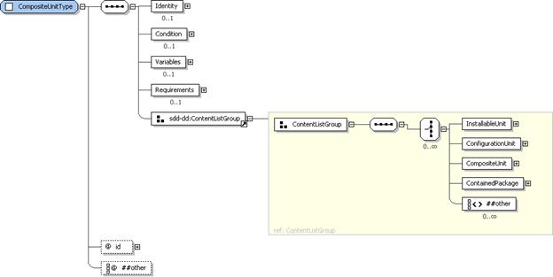
Figure 74: CompositeUnitType
structure.
The CompositeUnit
element is used to organize content elements within the base or selectable
content hierarchies. It can define any number of InstallableUnits, ConfigurationUnits,
ContainedPackages and other CompositeUnits. Composite units assist
in organizing the deployment package. A composite unit can provide a convenient
way to specify variables, requirements, conditions and other information that
applies to every content element defined below the composite unit. Within the
selectable content hierarchy, composite units can be used to group content
elements that are selected by feature sets or groups. When a feature containing
a composite unit is selected, all its child content elements are selected by
association. Organization of content within a composite unit does not imply any
relationships among the resources that result from deployment of the composite
content.
4.9.2.1 CompositeUnitType
Property Summary
|
Name
|
Type
|
*
|
Description
|
|
Identity
|
IdentityType
|
0..1
|
Human-understandable
identity information about the CompositeUnit.
|
|
Condition
|
ConditionType
|
0..1
|
A
condition that determines if the CompositeUnit and its child content elements
are relevant to a particular deployment.
|
|
Variables
|
VariablesType
|
0..1
|
Variables
for use within the CompositeUnit’s and its child content elements’
requirement and artifact definitions.
|
|
Requirements
|
RequirementsType
|
0..1
|
Requirements
that must be met prior to successful processing of any of the CompositeUnit’s
content.
|
|
InstallableUnit
|
InstallableUnitType
|
0..*
|
An
InstallableUnit that is part of the composite content.
|
|
ConfigurationUnit
|
ConfigurationUnitType
|
0..*
|
A
ConfigurationUnit that is part of the composite content.
|
|
CompositeUnit
|
CompositeUnitType
|
0..*
|
A
CompositeUnit that organizes a subset of the composite’s content.
|
|
ContainedPackage
|
ReferencedPackageType
|
0..*
|
A
ContainedPackage that is part of the composite content.
|
|
|
xsd:any
|
0..*
|
|
|
id
|
xsd:ID
|
1
|
An
identifier for the CompositeUnit scoped to the deployment descriptor.
|
|
|
xsd:anyAttribute
|
0..*
|
|
4.9.2.2 CompositeUnitType
Property Usage Notes
§
Identity:
This identity MAY have values in common with the identity of a resulting
resource created when artifacts defined by content of the composite are
processed.
If
the unit of packaging described by the CompositeUnit
is known to a package management system, some of the identity elements MAY
correspond to values associated with that package in the package management
system.
See
the IdentityType section for structure
and additional usage details [3.4].
§
Condition:
When the condition defined in the CompositeInstallable
is not met for a particular deployment, the CompositeUnit
and all the content elements defined below the CompositeUnit are out of scope for that particular deployment.
See
the ConditionType section for
structure and additional usage details [4.5.1].
§
Variables:
Variables defined here are visible within the CompositeUnit and every content element defined below the CompositeUnit.
These
variables are in scope for a particular deployment only if the CompositeUnit is in scope for that
deployment.
See
the VariablesType section for
structure and additional usage details [4.6.3].
§
Requirements:
These are requirements that must be met before any of the artifacts in the CompositeUnit hierarchy can be
processed.
These
requirements are in scope for a particular deployment only if the CompositeUnit is in scope for that
deployment.
The
operation defined for a Requirement defined in a CompositeUnit MUST be the same as the operation defined by the CompositeInstallable containing the CompositeUnit.
See
the RequirementsType section for
structure and additional usage details [4.7.1].
§
InstallableUnit:
See the InstallableUnitType section
for structure and additional usage details [4.3.1].
§
ConfigurationUnit:
See the ConfigurationUnitType section
for structure and additional usage details [4.3.2].
§
CompositeUnit:
A CompositeUnit element MAY contain
child CompositeUnits.
§
ContainedPackage:
See the ReferencedPackageType section
for structure and additional usage details [4.10.1].
§
id:
The id attribute may be useful to
software that processes the SDD, for example, for use in creating log and trace
messages.
SDD packages can aggregate other SDD
packages. Metadata about the aggregation is defined in ContainedPackage, ContainedLocalizationPackage
and Requisite elements. ContainedPackage elements are content
elements that can be defined anywhere in the base and selectable content
hierarchies. ContainedLocalizationPackages
are content elements that can be defined in the localization content hierarchy.
Requisites are packages that can be
deployed, if necessary, to satisfy requirements in the aggregating SDD. They
are not content of the SDD package. The type of all three of these elements is ReferencedPackageType. The term referenced package is used in this
specification when referring to these elements as a group. The term referenced SDD is used when referring to
any aggregated SDD.
When an SDD aggregates other SDDs, the
package descriptors of the aggregated SDDs are included in the Contents list in the package descriptor
of the aggregating SDD (see Figure
75). The referenced package elements in the deployment
descriptor identify a referenced SDD package by referencing its package
descriptor definition in Contents.
Each referenced package element can further constrain the deployment of the
referenced SDD by defining additional requirements; by mapping resources
defined in the aggregating SDD to those defined in the referenced SDD; and by
determining feature selections for deployment of the referenced SDD.
Figure 75: The aggregating SDD identifies the package descriptor of the
aggregated SDD and maps resource definitions in the aggregating SDD to resource
definitions in the aggregated SDD.
Referenced packages can create and modify
software resources that may be required by the aggregating SDD or other SDDs in
the aggregation. These resources are mapped to the associated resource
definitions in the aggregating SDD by using the ResultingResourceMap, the ResultingChangeMap
and the RequiredResourceMap elements
of a referenced package element. The characteristics of these resources that other
SDDs in the aggregation depend on in some way MUST be exposed in the ResultingResourceMap, the ResultingChangeMap and the RequiredResourceMap elements of the
aggregating SDD (see Figure 76). These exposed characteristics are mapped to
requirements, conditions and resource variables in the SDDs to determine if
requirements are satisfied, conditions are met and to set the values of
resource property variables (see Figure
77).
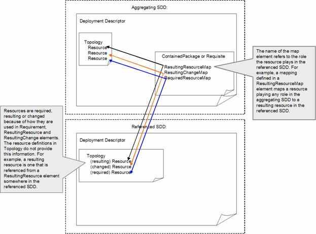
Figure 76: The list of resource maps is segmented by the role the resource
plays in the referenced SDD.
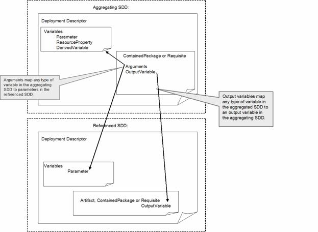
Figure 77: Arguments and OutputVariables of ReferencedPackageType map
variables in the aggregating SDD to variables in the referenced SDD.
Figure 78: ReferencedPackageType
structure.
A referenced package identifies an
aggregated SDD and describes the conditions of its aggregation. ReferencedPackageType provides the type
definition for ContainedPackage and Requisite elements. ContainedPackage elements identify an SDD package that is treated
like a content element of the defining SDD. Requisite
elements identify an SDD package that can be deployed, if necessary, to satisfy
resource constraints.
4.10.1.1 ReferencedPackageType
Property Summary
|
Name
|
Type
|
*
|
Description
|
|
Condition
|
ConditionType
|
0..1
|
A condition that determines if the
referenced package is relevant to a particular deployment.
|
|
RequiredContentSelection
|
RequiredContentSelectionType
|
0..1
|
A
list of groups and features that MUST be selected when the referenced package
is deployed.
|
|
Arguments
|
ArgumentListType
|
0..1
|
Inputs
to the reference package.
|
|
OutputVariables
|
OutputVariableListType
|
0..1
|
Outputs
from the referenced package.
|
|
Requirements
|
RequirementsType
|
0..1
|
Additional
requirements for deploying the referenced package as part of the aggregation.
|
|
ResultingResourceMap
|
ResultingResourceMapType
|
0..*
|
Maps
resulting resources in the referenced package to resources in the referencing
package and exposes properties of the resulting resource.
|
|
ResultingChangeMap
|
ResultingChangeMapType
|
0..*
|
Maps
changed resources defined in the referenced package to resources in the
referencing package and exposes changed properties of the resource.
|
|
RequiredResourceMap
|
ResourceMapType
|
0..*
|
Maps
required resources in the referenced package to resources in the referencing
package.
|
|
Languages
|
LanguagesType
|
0..1
|
Languages
supported by the referenced package.
|
|
|
xsd:any
|
0..*
|
|
|
id
|
xsd:ID
|
1
|
Identifier
for the referenced package element that is unique within the deployment
descriptor.
|
|
contentRef
|
xsd:token
|
1
|
Reference
to the identifier of the package Content defined in the package descriptor
which identifies the package descriptor of the referenced package.
|
|
weight
|
xsd:positiveInteger
|
0..1
|
The
time required to process the referenced package relative to all artifacts and
other referenced packages in the SDD.
|
|
operation
|
OperationType
|
0..1
|
Specifies
which operation in the referenced SDD is performed.
|
|
|
xsd:anyAttribute
|
0..*
|
|
4.10.1.2 ReferencedPackageType
Property Usage Notes
§
Condition:
A Condition is used when the ReferencedPackage’s content should only be
deployed when certain conditions exist in the deployment environment.
See the ConditionType
section for structure and additional usage details [4.5.1].
§
RequiredContentSelection:
Certain Groups or Features may need to be selected when
deploying the referenced package. These can be identified in the RequiredContentSelection element.
If
one particular aggregated SDD requires the selection of different groups or
features, depending on other choices made during a particular deployment,
different Requisite or ContainedPackage elements can be defined
in a way that will cause the correct combination of Groups and Features to be
used in each situation.
See
the RequiredContentSelectionType
section for structure and additional usage details [4.12.13].
§
Arguments:
Arguments are used to provide values for input variables defined in the
deployment descriptor of the referenced package. The argument name specified
MUST reference the id of a parameter
in the referenced package.
See
the ArgumentListType section for
structure and additional usage details [4.3.8].
§
OutputVariables:
The output variable mapping can be used to set variables to outputs created by
processing the referenced SDD. The output variables in the referenced package
are mapped to output variables in the aggregating SDD.
Each
output variable value specified MUST reference the id of an output variable in the referenced package. This can be an
output variable from an artifact or an output variable from a referenced
package defined within the referenced SDD.
See
the OutputVariableListType section
for structure and additional usage details [4.3.10].
§
Requirements:
When the aggregating SDD has stricter requirements for the use of the
referenced SDD than are defined by the referenced SDD itself, those
requirements can be defined in Requirements.
This is not intended to repeat requirements expressed in the referenced SDD,
but rather to add additional stricter requirements.
Requirements
expressed in the referenced SDD need to be satisfied, in addition to the
requirements expressed in the Requisite or ContainedPackage element of the
aggregating SDD.
Requirements
expressed in the aggregating SDD MUST NOT conflict with requirements expressed
in the referenced SDD. The requirements specified MUST further constrain the
referenced package.
See
the RequirementsType section for
structure and additional usage details [4.7.1].
§
ResultingResourceMap:
Resources created by the referenced package may be resources that are defined
in the aggregating SDD. The ResultingResourceMap
is used to identify the correspondence between resource definitions in the
aggregating SDD and resulting resource definitions in the aggregated SDD.
Characteristics
of the resulting resources MAY be exposed in the ResultingResourceMap element. ResourceConstraints
defined on those resources anywhere in the aggregation are mapped to the
resource properties exposed in the resulting maps of the referenced package to
determine if the referenced package will satisfy the constraints. Each
individual constraint is considered met by the referenced package if a property
exposed in the resulting resource map that is in scope for the particular
deployment satisfies the constraint.
For example, a property constraint in a ResourceConstraint element states that
the property named “FileAttributes” has the value “Writeable”. The
resourceRef in the ResourceConstraint identifies a resource
defined in Topology that is also
identified in the ResultingResourceMap
of a Requisite or ContainedPackage element that is in
scope for the particular deployment. If the ResultingResourceMap
element contains a statement that the property named “FileAttributes” has the
value “Writeable”, then the ResourceConstraint
is met when the Requisite or ContainedPackage is deployed.
This
same logic applies to ResourceConstraints
in aggregated packages. If the SDD in the preceding example also aggregates
another SDD and maps the same resource to a required resource in that
aggregated SDD, then all ResourceConstraints
in the aggregated SDD are met only if the ResultingResourceMap
of the referenced SDD that creates that resource contains a Name, Version or Property definition
that satisfies the constraint.
See
the ResultingResourceMapType section
for structure and additional usage details [4.10.3].
§
ResultingChangeMap:
Resources configured by the referenced package may be resources that are defined
in the aggregating SDD. The ResultingChangeMap
is used to identify the correspondence between resource definitions in the
aggregating SDD and changed resources defined in ResultingChange elements of the aggregated SDD.
Characteristics
of resources that are changed by the referenced SDD MAY be exposed in the ResultingChangeMap. These are correlated
with ResourceConstraints on the
changed resource in the same manner as the exposed characteristics of a
resulting resource. See the property usage notes for ResultingResourceMap above.
See
the ResultingChangeMapType section
for structure and additional usage details [4.10.4].
§
RequiredResourceMap:
When a resource required by the aggregated SDD is a resource also defined in
the aggregating SDD, the RequiredResourceMap
is used to identify the correspondence. This element is a simple mapping of a
resource in one SDD to a resource in another. There is no need to expose
characteristics of the resource because it is not created or modified by the
referenced package.
One
resource MAY be required, resulting, changed, all three or any combination of
these within one SDD. When a resource in the referenced SDD plays more than one
role, the mapping MUST be repeated everywhere it applies. This allows exposure
of all the created or modified properties in the ResultingChangeMap and ResultingResourceMap.
In this situation–when one resource in the referenced SDD plays more than one of the roles identified
earlier (required, resulting or changed)–all mappings MUST be to the
same resource in the aggregating SDD. Only the exposed resulting and changed
properties differ.
See
the ResourceMapType section for
structure and additional usage details [4.10.2].
§
Languages:
Languages supported by the referenced package MAY be identified here. This list
does not identify mandatory versus optional languages; it is for informational
purposes only. The SDD author is not limiting use of the referenced package to
deployments where all in-scope languages are found in this list. There may be
cases where aggregated packages are deployed even though they cannot support
all of the languages supported by the aggregation as a whole.
Each
language specified MUST match a language in the referenced package.
See
the LanguagesType section for
structure and additional usage details [4.13.6].
§
id:
The id attribute may be useful to
software that processes the SDD, for example, for use in creating log and trace
messages.
§
contentRef: The package descriptor of an SDD that
aggregates other SDDs, either through ContainedPackage
elements or Requisite elements, will
list the package descriptor files of the aggregated SDDs in its content list.
The contentRef attribute of a
referenced package element MUST be a reference to the id of a Content element
in the aggregating SDD’s package descriptor that defines the aggregated package
descriptor.
§
weight:
Defining weights for all artifacts and referenced packages in an SDD provides
useful information to software that manages deployment. The weight of the
referenced package refers to the relative time taken to deploy the referenced
package with respect to other packages in this SDD.
For example, if the referenced package takes
twice as long to deploy as a particular install artifact whose weight is “4”,
then the weight of the referenced package would be “8”. The weight numbers have
no meaning in isolation and do not describe actual time elapsed. They simply
provide an estimate of relative time.
§
operation:
The referenced SDD may support more than one deployment lifecycle operation.
The operation attribute MUST include
the operations that are applicable when this is the case.
See
the OperationType section for enumeration
values and their meaning [4.3.7].
Figure 79: ResourceMapType
structure.
ResourceMapType
is used in the definition of elements that map resources in an SDD to resources
in a referenced SDD. The purpose of a resource map is to identify when two
resources in separate SDDs MUST resolve to the same resource instance during
any particular deployment. The characteristics of a mapped resource that are
defined in the topology sections of the two SDDs MUST NOT conflict.
For example, if a Name is defined for the resource in both topologies, it MUST be the
same in both definitions and if a Property
definition is included for the same property in both places, the value MUST be
the same.
Additional characteristics of a mapped resource
may be constrained by Requirements or
Conditions in either SDD. All
constraints on a mapped resource that are in scope for a particular deployment
MUST NOT conflict.
Resources that are not mapped between the
two SDDs MAY resolve to the same instance when their characteristics defined in
topology do not conflict and when the constraints in scope for any particular
deployment do not conflict.
The RequiredResourceMap,
ResultingResourceMap and ResultingChangeMap elements all use ResourceMapType, either directly or as a
base type that is extended.
4.10.2.1 ResourceMapType
Property Summary
|
Name
|
Type
|
*
|
Description
|
|
resourceRef
|
xsd:IDREF
|
1
|
Reference
to a resource defined in the deployment descriptor.
|
|
foreignID
|
xsd:NCName
|
0..1
|
Reference
to a resource defined in a referenced deployment descriptor.
|
|
|
xsd:anyAttribute
|
0..*
|
|
4.10.2.2 ResourceMapType
Property Usage Notes
§
resourceRef:
The value of the resourceRef MUST be set
to the id of the resource in the SDD to
be mapped to a resource in a referenced
SDD.
§
foreignID:
The value MUST reference the id of a
resource in the referenced package. This is the resource in the referenced SDD
that MUST resolve to the same resource instance as the resource identified in resourceRef.
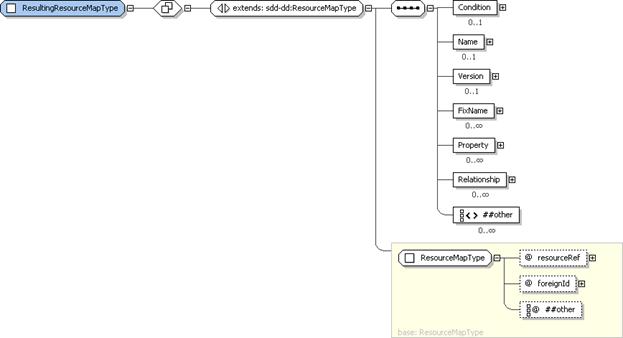
Figure 80:
ResultingResourceMapType structure.
ResultingResourceMapType
defines an element type that maps resources that result from deployment of the
referenced SDD to a resource in the referencing SDD. In addition to identifying
the two resources that MUST resolve to the same resource instance, the
resulting resource map allows characteristics of the resulting resource to be
exposed. There may be constraints defined on the mapped resource in the
referencing SDD or any referenced SDD in the hierarchy of SDDs. These
constraints can be evaluated by comparing the constraint to the exposed
characteristics defined in the resulting resource map. The resulting resource
map MUST expose sufficient characteristics of the resulting resource to support
successful evaluation of constraints on that resource.
For example, say that the SDD defines a
resource with id=”Database” in its topology. The solution can work with
Database Product A or Database Product B. Database Product A is created by a
referenced SDD defined in a Requisites
element. The SDD will contain Requirements
and/or Conditions that have
alternatives for each of the database products. All constraints on the Database
resource that apply to Database Product A must be satisfied by a resource
characteristic exposed in the ResultingResourceMap
element of the Requisite element that
points to the SDD that deploys Database Product A.
4.10.3.1 ResultingResourceMapType
Property Summary
|
Name
|
Type
|
*
|
Description
|
|
|
[extends]
ResourceMapType
|
|
See
the ResourceMapType section for additional properties [4.10.2].
|
|
Condition
|
ConditionType
|
0..1
|
A
condition that determines if the resulting resource definition is relevant to
a particular deployment.
|
|
Name
|
VariableExpressionType
|
0..1
|
The
name of the resource created or updated by the referenced SDD.
|
|
Version
|
VersionType
|
0..1
|
The
version of the resource created or updated by the referenced SDD.
|
|
FixName
|
xsd:string
|
0..*
|
Names
of fixes to the mapped resource that are created by the referenced SDD.
|
|
Property
|
ResultingPropertyType
|
0..*
|
Properties
set when the mapped resource is created or updated by the referenced SDD.
|
|
Relationship
|
RelationshipType
|
0..*
|
Relationship
that will exist after creating or updating the resource.
|
|
|
xsd:any
|
0..*
|
|
4.10.3.2 ResultingResourceMapType
Property Usage Notes
See the ResourceMapType
section for details of the inherited attributes and elements [4.10.2].
§
Condition:
A Condition is used when the
resulting resource will be created by the referenced package only when certain
conditions exist in the deployment environment.
See
the ConditionType section for
structure and additional usage details [4.5.1].
§
Name:
The Name of the resulting resource
created or updated by the referenced SDD MUST be defined if it is not defined
elsewhere and there are constraints on this resource that contain a Name element. “Defined elsewhere” means
defined in the topology of the referencing SDD or in the topology of any other
referenced SDD for a resource that is also mapped to the same resource.
“Constraints on this resource” means a constraint that applies to the
particular instantiation of the resource that is created or updated by the
referenced SDD, for example a constraint that needs to successfully map to the
referenced SDD for the referenced SDD to be used in a particular deployment.
See
the VariableExpressionType section
for structure and additional usage details [4.6.1].
§
Version:
The Version of the resulting resource
created or updated by the referenced SDD MUST be defined if it is not defined
elsewhere and there are version constraints defined on this resource. (See the
usage note for Name above for a
definition of “defined elsewhere”.)
See
the VersionType section for structure
and additional usage details [3.10].
§
FixName:
One or more names of fixes to the resulting resource created or updated by the
referenced SDD MUST be defined if they are not defined elsewhere and there are
version constraints defined on this resource that include fix names. (See the
usage note for Name above for a
definition of “defined elsewhere”.)
§
Property:
A Property of the resulting resource
created or updated by the referenced SDD MUST be defined if it is not defined
elsewhere and there are property constraints on this property. (See the usage
note for Name above for a definition
of “defined elsewhere”.)
See
the ResultingPropertyType section for
structure and additional usage details [4.2.4].
§
Relationship:
Any number of Relationship elements
can be included to identify relationships that will exist after applying the
referenced package.
See the RelationshipType
section for structure and additional usage details [4.8.3].
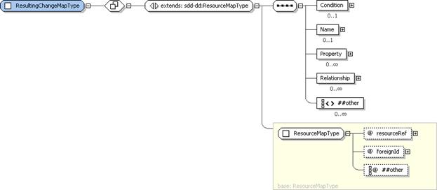
Figure 81:
ResultingChangeMapType structure.
ResultingChangeMapType
is very similar to ResultingResourceMapType.
It defines an element type that maps resources that are changed by deployment
of the referenced SDD to a resource in the referencing SDD. In addition to
identifying the two resources that MUST resolve to the same resource instance,
the resulting change map allows characteristics of the modified resource to be
exposed. There may be constraints defined on the mapped resource in the
referencing SDD or any referenced SDD in the hierarchy of SDDs. These
constraints can be evaluated by comparing the constraint to the exposed
characteristics defined in the resulting change map. The resulting change map
MUST expose sufficient characteristics of the resulting change to support
successful evaluation of constraints on that resource.
For example, say that the SDD defines a
resource with id=”OS” in its topology. The solution can work with Windows or
Linux. Linux is configured by a referenced SDD defined in a Requisites element. The SDD will contain
Requirements and/or Conditions that have alternatives for
Windows and for Linux. All constraints on the modified characteristics of Linux
must be satisfied by a resource characteristic exposed in the ResultingChangeMap element of the Requisite element that points to the SDD
that configures Linux.
4.10.4.1 ResultingChangeMapType
Property Summary
|
Name
|
Type
|
*
|
Description
|
|
|
[extends]
ResourceMapType
|
|
See
the ResourceMapType section for additional properties [4.10.2].
|
|
Condition
|
ConditionType
|
0..1
|
A
condition that determines if the resulting change definition is relevant to a
particular deployment.
|
|
Name
|
VariableExpressionType
|
0..1
|
The
name of the modified resource.
|
|
Property
|
ResultingPropertyType
|
0..*
|
A
modified property of the resource.
|
|
Relationship
|
RelationshipType
|
0..*
|
Relationship
that will exist after the change is applied to the resource.
|
|
|
xsd:any
|
0..*
|
|
4.10.4.2 ResultingChangeMapType
Property Usage Notes
See the ResourceMapType
section for details of the inherited attributes and elements [4.10.2].
§
Condition:
A Condition is used when the resource
mapped from the external package will be changed only when certain conditions
exist in the deployment environment.
See the ConditionType
section for structure and additional usage details [4.5.1].
§
Name:
The Name of the resource that is
modified by the referenced SDD is defined here to assist with identifying the
resource instance that is changed. It is not an indication that the resource
name itself is modified by the referenced SDD. If resource characteristics
defined in the topology of any SDD defining a resource mapped to the changed
resource are sufficient to identify the resource, then Name SHOULD NOT be defined in the ResultingChangeMap.
See the VariableExpressionType
section for structure and additional usage details [4.6.1].
§
Property:
A modified property MUST be exposed in a ResultingChangeMap
if it is not defined elsewhere and there are property constraints on the
modified property. “Defined elsewhere” means defined in the topology of the
referencing SDD or in the topology of any other referenced SDD for a resource
that is also mapped to the same resource. “Constraints on the modified
property” means a property constraint that applies to the particular
instantiation of the resource that is modified by the referenced SDD, for
example a constraint that needs to successfully map to the referenced SDD for
the referenced SDD to be used in a particular deployment.
See
the ResultingPropertyType section for
structure and additional usage details [4.2.4].
§
Relationship: Relationship elements SHOULD be
included to identify relationships that will exist after the application of the
referenced package.
Relationships
that need to be known by the aggregate MUST be mapped. Relationships need to be
known when they are referred to in one or more resource constraints.
See the RelationshipType
section for structure and additional usage details [4.8.3].

Figure 82: RequisitesType
structure.
The Requisites
element contains a list of references to SDD packages that can be used to
satisfy one or more of the requirements defined by content elements. The
definition of a requisite does not imply that it must be used; only that it is
available for use if needed.
Requisite definitions can map values and
resources defined in the SDD to inputs and resources defined in the requisite
SDD.
4.10.5.1 RequisitesType
Property Summary
|
Name
|
Type
|
*
|
Description
|
|
ReferencedPackage
|
ReferencedPackageType
|
1..*
|
An
SDD package that can, but is not required to, be deployed to satisfy a
requirement.
|
4.10.5.2 RequisitesType
Property Usage Notes
§
ReferencedPackage:
See the ReferencedPackageType section
for structure and additional usage details [4.10.1].
Base content is the default content for the
deployment lifecycle operation associated with the CompositeInstallable that contains the base content. This is
content that is deployed whenever the associated operation is performed on the
SDD package. Base content may be conditioned on characteristics of the
deployment environment but it is not selectable by the deployer.
Resources associated with base content for
one operation may be different from resources associated with base content for
a different operation in the same SDD package.
For example, base content in the CompositeInstallable for the
configuration operation may configure resources that were created by selectable
content in the CompositeInstallable
for the install operation. In this example, the configuration is in base
content because it must be done if the resource exists. It is not selectable by
the deployer during the configuration operation.
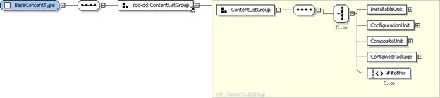
Figure 83: BaseContentType
structure.
The BaseContent
hierarchy defines the default content for the deployment operation described by
the CompositeInstallable. This
content MAY be conditioned.
4.11.1.1 BaseContentType
Property Summary
|
Name
|
Type
|
*
|
Description
|
|
InstallableUnit
|
InstallableUnitType
|
0..*
|
An
InstallableUnit that defines base content.
|
|
ConfigurationUnit
|
ConfigurationUnitType
|
0..*
|
A
ConfigurationUnit that defines base configuration content.
|
|
CompositeUnit
|
CompositeUnitType
|
0..*
|
A
CompositeUnit that organizes base content.
|
|
ContainedPackage
|
ReferencedPackageType
|
0..*
|
An
SDD whose content is considered to be base content in the context of this
aggregation.
|
|
|
xsd:any
|
0..*
|
|
4.11.1.2 BaseContentType
Property Usage Notes
§
InstallableUnit:
See the InstallableUnitType section
for structure and additional usage details [4.3.1].
§
ConfigurationUnit:
See the ConfigurationUnitType section
for structure and additional usage details [4.3.2].
§
CompositeUnit:
See the CompositeUnitType section for
structure and additional usage details [4.9.2].
§
ContainedPackage:
See the ReferencedPackageType section
for structure and additional usage details [4.10.1].
The SDD author MAY define selectable subsets
of content using Groups and Features. Selectability, as used in the
SDD, is a characteristic of the deployment lifecycle operation and the package.
The decision to provide selectability for one operation in one package has no
semantic relationship to the selectability provided in another package related
to the same software. It also has no semantic relationship to the selectability
provided for a different operation within the same package.
For example, when the SDD author chooses to
create a feature in a maintenance package, that feature is designed to allow
selectable application of the maintenance, not to reflect the original set of
features for the base content.
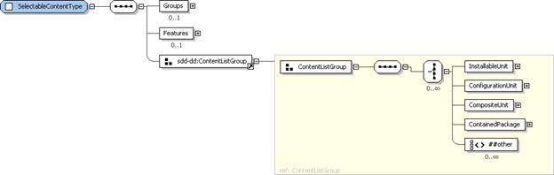
Figure 84: SelectableContentType
structure.
Content elements defined here make up the
selectable content hierarchy. These elements are selected via Groups and Features also defined under SelectableContent.
4.12.1.1 SelectableContentType
Property Summary
|
Name
|
Type
|
*
|
Description
|
|
Groups
|
GroupsType
|
0..1
|
Groups
of features that can be selected as a unit.
|
|
Features
|
FeaturesType
|
0..1
|
A
definition of user-selectable content.
|
|
InstallableUnit
|
InstallableUnitType
|
0..*
|
An
InstallableUnit that defines selectable content.
|
|
ConfigurationUnit
|
ConfigurationUnitType
|
0..*
|
A
ConfigurationUnit that defines selectable configuration.
|
|
CompositeUnit
|
CompositeUnitType
|
0..*
|
A
CompositeUnit that organizes content elements that define selectable content.
|
|
ContainedPackage
|
ReferencedPackageType
|
0..*
|
An
SDD package whose content is selectable in the context of the aggregating
SDD.
|
|
|
xsd:any
|
0..*
|
|
4.12.1.2 SelectableContentType
Property Usage Notes
§
Groups:
Groups can be used by the SDD author
to define a convenient way for deployers to select a group of features.
“Typical” and “Custom” are examples of
groups that are commonly presented in installation interfaces.
See
the GroupsType section for structure
and additional usage details [4.12.2].
§
Features:
Features can be used to organize
optional functionality into meaningful selections. Features should be meaningful from the deployer’s point of view.
See
the FeaturesType section for
structure and additional usage details [4.12.4].
§
InstallableUnit:
See the InstallableUnitType section
for structure and additional usage details [4.3.1].
§
ConfigurationUnit:
See the ConfigurationUnitType section
for structure and additional usage details [4.3.2].
§
CompositeUnit:
See the CompositeUnitType section for
structure and additional usage details [4.9.2].
§
ContainedPackage:
See the ReferencedPackageType section
for structure and additional usage details [4.10.1].

Figure 85: Groups structure.
GroupsType
is used in SelectableContent to provide
a list of one or more Group elements.
4.12.2.1 GroupsType
Property Summary
|
Name
|
Type
|
*
|
Description
|
|
Group
|
GroupType
|
1..*
|
A
group of features that can be selected together.
|
4.12.2.2 GroupsType
Property Usage Notes
§
Group:
Associating features in a Group is
based on the characteristics of the package and the ways in which the SDD
author chooses to expose function variability to the deployer.
One example is a “Typical” group that allows
easy selection of the most common grouping of features, along with a “Custom”
group that allows an advanced user to select from among all features. Another
example is a “Client” group that selects features that deploy the client
software for an application, along with a “Server” group that selects features
that deploy the server software for the same application.
If
alternative sets of selections are desired, Groups MUST be used to define these
sets. Zero or one set can be selected
for any particular deployment
See
the GroupType section for structure
and additional usage details [4.12.3].
Figure 86: GroupType structure.
GroupType
provides the type definition for each Group
element in SelectableContent’s list
of Groups. For a particular
deployment, zero or one groups may be selected by the deployer.
4.12.3.1 GroupType
Property Summary
|
Name
|
Type
|
*
|
Description
|
|
DisplayName
|
DisplayTextType
|
0..1
|
A
human-readable name for the group.
|
|
Description
|
DisplayTextType
|
0..1
|
A
human-readable description of the group.
|
|
ShortDescription
|
DisplayTextType
|
0..1
|
A
human-readable short description of the group.
|
|
SelectedFeature
|
FeatureReferenceType
|
1..*
|
A
feature that is part of the group.
|
|
|
xsd:any
|
0..*
|
|
|
id
|
xsd:ID
|
1
|
An
identifier of the group that is unique within the descriptor.
|
|
default
|
xsd:boolean
|
0..1
|
Indicates
that the group is selected by default when no selections are provided by the
deployer.
**default
value=“false”
|
|
|
xsd:anyAttribute
|
0..*
|
|
4.12.3.2 GroupType
Property Usage Notes
§
DisplayName:
This element MAY be
used to provide human-understandable information. If used, it MUST
provide a label for the group.
See
the DisplayElementGroup section for
structure and additional usage details [4.14.2].
§
Description,
ShortDescription: These elements MAY be
used to provide human-understandable information. If used, they MUST
provide a description of the group.
The
Description element MUST be defined
if the ShortDescription element is
defined.
See
the DisplayElementGroup section for
structure and additional usage details [4.14.2].
§
SelectedFeature:
Each SelectedFeature is considered
selected if inputs identify the group as selected.
Selection
of a nested feature causes its parent feature to be selected.
See the FeatureReferenceType
section for structure and additional usage details [4.12.8].
§
id:
The group’s id may be used to refer
to the group when aggregating the SDD into another SDD.
The id
attribute may be useful to software that processes the SDD, for example, for
use in creating log and trace messages.
§
default:
Multiple default Groups MUST NOT be
defined.
Figure 87: FeaturesType
structure.
FeaturesType
provides the type definition for the single, optional, Features element in SelectableContent.
Features defined directly under the Features
element in SelectableContent are the top
level features. A Features element may
also include a MultiSelect element that
refers to features whose selections are interdependent.
4.12.4.1 FeaturesType
Property Summary
|
Name
|
Type
|
*
|
Description
|
|
Feature
|
FeatureType
|
1..*
|
A
top level feature in the hierarchy of features defined in SelectableContent.
|
|
MultiSelect
|
MultiSelectType
|
0..*
|
A
list of feature references whose selection is controlled as a multi-select
list with defined minimum and maximum selections.
|
|
|
xsd:any
|
0..*
|
|
4.12.4.2 FeaturesType
Property Usage Notes
§
Feature:
Each top level Feature can define NestedFeatures. All features can define
required relationships with other features that cause the required feature to
be selected.
See
the FeatureType section for structure
and additional usage details [4.12.5].
§
MultiSelect:
The MultiSelect element MUST refer to
Feature or NestedFeature elements.
See
the MultiSelectType section for
structure and additional usage details [4.12.15].
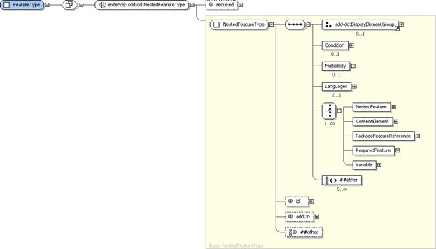
Figure 88: FeatureType
structure.
FeatureType
provides the type definition for each feature defined directly below SelectableContent. A Feature can define NestedFeatures and identify ContentElements
and other features that will be selected when the feature is selected. A
feature can also be defined to be available for selection only under certain
conditions.
4.12.5.1 FeatureType
Property Summary
|
Name
|
Type
|
*
|
Description
|
|
|
[extends]
NestedFeatureType
|
|
See
the NestedFeatureType section for additional properties [4.12.6].
|
|
required
|
xsd:boolean
|
0..1
|
Indicates
the feature must be selected.
**default
value=“false”
|
4.12.5.2 FeatureType
Property Usage Notes
See the NestedFeatureType
section for details of the inherited attributes and elements [4.12.6].
§
required:
A top level Feature MUST be selected
when the value of the required
attribute is “true”. In this case, the user cannot choose to deselect this top level
Feature.
In Features that define Multiplicity, the SDD author can state a
minimum number of instances of the Feature.
This minimum applies only if the Feature
is selected. The required attribute
can be used to indicate that the Feature
is always selected and so the minimum number of instances applies.
The
required attribute SHOULD be used
only when Multiplicity is applied to
the Feature.
Figure 89: NestedFeatureType
structure.
NestedFeatureType
is identical to FeatureType except
that NestedFeatureType does not define
a required attribute. All features
other than those defined directly below SelectableContent
use the NestedFeatureType.
4.12.6.1 NestedFeatureType
Property Summary
|
Name
|
Type
|
*
|
Description
|
|
DisplayName
|
DisplayTextType
|
0..1
|
A
human-readable name for the feature.
|
|
Description
|
DisplayTextType
|
0..1
|
A
human-readable description of the feature.
|
|
ShortDescription
|
DisplayTextType
|
0..1
|
A
human-readable short description of the feature.
|
|
Condition
|
ConditionType
|
0..1
|
A
condition that determines if the feature is relevant to a particular
deployment.
|
|
Multiplicity
|
MultiplicityType
|
0..1
|
Both an indication that multiple instances of the
feature can be selected and the specification of their constraints.
|
|
Languages
|
LanguageSelectionsType
|
0..1
|
A
list of language support available for the feature’s content.
|
|
NestedFeature
|
NestedFeatureType
|
0..*
|
A
nested feature.
|
|
ContentElement
|
ContentElementReferenceType
|
0..*
|
A
reference to a content element to be deployed when the feature is selected.
|
|
PackageFeatureReference
|
PackageFeatureReferenceType
|
0..*
|
A
reference to a feature to be selected in a ContainedPackage defined in either
the BaseContent or SelectableContent hierarchies.
|
|
RequiredFeature
|
FeatureReferenceType
|
0..*
|
A
reference to a feature that is required when the defining feature is selected
and so is selected automatically.
|
|
Variable
|
DerivedVariableType
|
0..*
|
The
definition of a variable that can be used anywhere in any variable expression
in the SDD.
|
|
|
xsd:any
|
0..*
|
|
|
id
|
xsd:ID
|
1
|
Used
within the SDD to refer to the feature.
|
|
addOn
|
xsd:boolean
|
0..1
|
A
“true” value indicates that the feature can be added to a deployed instance
of the solution.
**default
value=“false”
|
|
|
xsd:anyAttribute
|
0..*
|
|
4.12.6.2 NestedFeatureType
Property Usage Notes
§
DisplayName:
This element MAY be
used to provide human-understandable information. If used, it MUST
provide a label for the nested feature.
See the DisplayElementGroup
section for structure and additional usage details [4.14.2].
§
Description,
ShortDescription: These elements MAY be
used to provide human-understandable information. If used, they MUST
provide a description of the nested feature.
The
Description element MUST be defined
if the ShortDescription element is
defined.
See
the DisplayElementGroup section for
structure and additional usage details [4.14.2].
§
Condition:
If the features and its nested features are only applicable in certain
environments, a Condition can be defined.
When the Condition is not met, the
feature and its nested features are not in scope.
For example, some features may be available only
on a Linux operating system, even though the software can be applied on other
operating systems. In this case, a Condition
can be defined to cause the feature to be ignored when the operating system is
not Linux.
See the ConditionType
section for structure and additional usage details [4.5.1].
§
Multiplicity:
When multiple instances of a feature can be selected, a Multiplicity element MUST be defined.
For example, a solution that includes a
server and a client may allow the deployment of multiple clients. In this
situation, a feature that defines a Multiplicity
element would select the content elements that deploy the client software.
See
the MultiplicityType section for
structure and usage details [4.12.7].
§
Languages:
Sometimes language support for a feature is different than that available for
the overall solution. This is especially likely when features are implemented
by aggregation of packages provided by different teams. When language support
differs, the Languages element of the
feature MUST be defined to state which languages are supported for the feature.
When Languages
is defined in a feature, it overrides the global declaration of supported
languages and MUST declare the complete set of language support available for
that feature.
If Languages is not defined, the global
declaration of supported languages in CompositeInstallable
applies for the feature.
See the LanguageSelectionsType
section for structure and additional usage details [4.13.4].
§
NestedFeature:
A NestedFeature must be explicitly
selected. It is not assumed to be selected when the parent feature is selected.
Selection of a nested feature causes its parent feature to be selected, but not
vice-versa. The definition of a NestedFeature
indicates that application of the NestedFeature
is dependent on application of the parent feature.
§
ContentElement:
The ContentElement referred to MUST
be in the selectable content hierarchy defined by the SelectableContent element.
When the content reference is to a CompositeUnit, the composite and all
content elements below it in the content hierarchy are considered to be in
scope when the feature is selected. Ease of referencing a group of content from
a feature can be one reason for using a composite in the content hierarchy.
See the ContentElementReferenceType
section for structure and additional usage details [4.12.9].
§
PackageFeatureReference:
Selection of a feature may result in selection of an aggregated package’s
feature identified by a ContainedPackage
element anywhere in the BaseContent
or SelectableContent hierarchies. A PackageFeatureReference identifies both
the ContainedPackage and the
applicable features to be selected in that package.
See the PackageFeatureReferenceType
section for structure and additional usage details [4.12.10].
§
RequiredFeature:
When the selection of one feature requires the selection of another feature,
the RequiredFeature can be used to specify
this requirement.
When two features identify each other as
required features, they are always selected together.
The selection of the defining feature MUST
cause the required feature to be selected.
See the FeatureReferenceType
section for structure and additional usage details [4.12.8].
§
Variable:
Variables defined in features are useful
when inputs to an artifact need to vary based on which features are selected
for a particular deployment. Artifact arguments can be defined in terms of
feature Variables to allow for this
variation. When an artifact deploys selectable content, inputs to the artifact
that indicate the selections for a particular deployment can be associated with
feature selection in the SDD via feature Variables.
For example, a Feature that deploys a trace facility might define a Variable called “TraceSettings”. The value
of an argument to a base content artifact might define its value as
“$(TraceSettings)”. If the feature is selected, this argument would be used and
its value would be taken from the feature Variable.
If the feature is not selected, the argument would be ignored.
A Variable defined in a feature
differs from Variable elements defined in content elements in one
important way. A reference to an undefined feature Variable is treated
as an empty string and is considered to be defined.
See the DerivedVariableType
section for structure and additional usage details [4.6.13].
§
id:
Provides the means to reference a feature from other features.
The id
attribute may be useful to software that processes the SDD, for example, for
use in creating log and trace messages.
§
addOn:
When a solution and the artifacts that deploy the various parts of the solution
are designed in a way that supports the addition of a particular feature at a later time (after the deployment
of the base solution), the addOn
attribute is set to “true”.

Figure 90: MultiplicityType
structure.
Some solutions allow multiple instances of
some portion of the solution’s resources to be deployed as part of the
solution.
For example, a solution that includes a
server and a client may allow the deployment of multiple clients. The
deployment of each client may involve content elements that represent several
different resulting resources, features that control optional functionality of
the client and configuration elements that configure the client. All of these
can be defined within a “Client” feature that declares a Multiplicity element that indicates that multiple clients are
allowed. Each selection or “instance” of the feature results in the deployment
of a client.
The phrase “feature instance” is used to
refer to the set of instances of all resources deployed when the feature is
selected. It does not imply that features themselves are represented as having
lifecycle or that features in the SDD
correspond with feature instances in the deployment environment.
4.12.7.1 MultiplicityType
Property Summary
|
Name
|
Type
|
*
|
Description
|
|
ConstrainedFeature
|
FeatureReferenceType
|
0..*
|
A
nested feature whose selection must be the same for all instances of the
defining feature in a particular deployment.
|
|
ConstrainedResource
|
ConstrainedResourceType
|
0..*
|
A
resource that must resolve to the same resource instance for all instances of
the feature in a particular deployment.
|
|
|
xsd:any
|
0..*
|
|
|
multiplesAllowed
|
xsd:boolean
|
1
|
Indicates
that multiple instances of the feature are allowed.
**fixed
value=“true”
|
|
minSelections
|
xsd:positiveInteger
|
0..1
|
The
minimum number of instances of the feature that must be selected if the feature
is selected at all.
**default
value=“1”
|
|
maxSelections
|
xsd:positiveInteger
|
0..1
|
That
maximum number of instances of the feature that can be selected.
|
|
|
xsd:anyAttribute
|
0..*
|
|
4.12.7.2 MultiplicityType
Property Usage Notes
§
ConstrainedFeature:
A feature with multiplicity may contain NestedFeature
elements. When a NestedFeature is
identified in a ConstrainedFeature,
then all instances of the defining Feature
MUST make the same selection choice for that NestedFeature.
See
the FeatureReferenceType section for
structure and additional usage details [4.12.8].
§
ConstrainedResource:
The content elements selected by a feature may express constraints on
resources. When the resource constraints for each instance of a feature must
resolve to the same resource instance, or when all must resolve to unique
resource instances, the resource is referred to and the constraint type is
identified in the ConstrainedResource
element.
See
the ConstrainedResourceType section
for structure and additional usage details [4.12.11].
§
multiplesAllowed:
This is an attribute with a fixed value of “true”. It is included because all
other elements and attributes of MultiplicityType
are optional. A feature that allows multiples but has no need to define
constraints on resources, features or number of instances would define a Multiplicity element that had only the multiplesAllowed attribute.
§
minSelections:
When a feature is selected, if more than one instance of the feature is
required, minSelections MUST be
specified.
§
maxSelections:
When a feature is selected, if there is a limit on the number of instances of the
feature that can be selected, maxSelections
MUST be specified. If maxSelections
is defined, it MUST be equal to or greater than minSelections.
Figure 91: FeatureReferenceType
structure.
FeatureReferenceType
provides a way to reference a feature defined in the SDD from within the SDD.
4.12.8.1 FeatureReferenceType
Property Summary
|
Name
|
Type
|
*
|
Description
|
|
featureRef
|
xsd:IDREF
|
1
|
Reference
to a feature defined in the deployment descriptor.
|
|
|
xsd:anyAttribute
|
0..*
|
|
4.12.8.2 FeatureReferenceType
Property Usage Notes
§
featureRef:
The value MUST reference the id of a feature
in the deployment descriptor.

Figure 92:
ContentElementReferenceType structure.
ContentElementReferenceType
provides a way to reference a content element defined in the SDD from within a feature.
4.12.9.1 ContentElementReferenceType
Property Summary
|
Name
|
Type
|
*
|
Description
|
|
contentElementRef
|
xsd:IDREF
|
1
|
Reference
to a content element in the deployment descriptor’s selectable content.
|
|
|
xsd:anyAttribute
|
0..*
|
|
4.12.9.2 ContentElementReferenceType
Property Usage Notes
§
contentElementRef:
The value MUST reference the id of a
content element in the deployment descriptor.
Figure 93:
PackageFeatureReferenceType structure.
PackageFeatureReferenceType
provides a way to reference a feature defined in a referenced SDD. It
identifies the ContainedPackage
element that references the SDD and the feature in the referenced SDD.
4.12.10.1 PackageFeatureReferenceType
Property Summary
|
Name
|
Type
|
*
|
Description
|
|
contentElementRef
|
xsd:IDREF
|
1
|
Reference
to a content element in the deployment descriptor.
|
|
packageFeatureRef
|
xsd:NCName
|
1
|
The feature’s id as defined in the referenced
package’s deployment descriptor.
|
|
|
xsd:anyAttribute
|
0..*
|
|
4.12.10.2 PackageFeatureReferenceType
Property Usage Notes
§
contentElementRef: This value MUST reference the id of a ContainedPackage element
in SelectableContent or BaseContent. This reference does not
cause the ContainedPackage to be in scope.
§
packageFeatureRef: Specifies the value of the id of a feature element from the SDD of
the ContainedPackage identified in contentElementRef. This
feature reference is ignored when the ContainedPackage identified in contentElementRef
is not in scope for a particular deployment.
Figure 94:
ConstrainedResourceType structure.
A resource may be required during deployment
of the content selected by a Feature
instance. The requirement may exist because the resource is used in a Requirement statement, referred to in a Variable whose value is in scope for the
particular deployment or referred to in a constraint in a Condition that is satisfied for the particular deployment. This is
an in-scope, required resource for the particular deployment. The SDD author
may wish to constrain in-scope, required resources to resolve to the same
resource instance for all Feature
instances or to resolve to unique resource instances for each Feature instance. This is done using a ConstrainedResource element.
4.12.11.1 ConstrainedResourceType
Property Summary
|
Name
|
Type
|
*
|
Description
|
|
resourceRef
|
xsd:IDREF
|
1
|
A
reference to the constrained resource.
|
|
constraintType
|
MultiplicityConstraintType
|
0..1
|
Indicates
whether the constraint requires every instance of the resource to be the same
or requires every instance to be different.
**default
value=“same”
|
|
|
xsd:anyAttribute
|
0..*
|
|
4.12.11.2 ConstrainedResourceType
Property Usage Notes
§
resourceRef:
The value MUST reference the id of a
resource element in Topology.
§
constraintType:
If there is a constraint, constraintType
indicates that all resource instances be unique or that all resource instances
be the same.
For example, all clients for a particular solution
may need to connect to the same database. In this case, constraintType would be set to same.
In other cases, each of the deployed resources might need to use its own unique
instance of a required resource. If there could be only one client per
operating system, a constraint on the operating system resource would set constraintType to unique.
See the MultiplicityConstraintType
section for the enumeration values for constraintType
[4.12.12].
This is a simple type that is used to
indicate how resources declared in the Multiplicity
element should be treated. Enumeration values are same, unique, or if a
value is not specified, the SDD author is indicating that it doesn’t
matter.
4.12.12.1 MultiplicityConstraintType
Property Usage Notes
§
same:
The value same is used to indicate
that the constraint requires all resource instances MUST be the same.
§
unique:
The value unique is used to indicate
that each resource instance MUST be unique.
Figure 95:
RequiredContentSelectionType structure.
When one SDD aggregates another, there needs
to be an indication of which Groups
and/or Features in the aggregated SDD
should be selected. The RequiredContentSelection
of the referenced package element identifies which elements MUST be selected
when the defining package is selected.
4.12.13.1 RequiredContentSelectionType
Property Summary
|
Name
|
Type
|
*
|
Description
|
|
Group
|
xsd:token
|
0..1
|
A
reference to the group to be selected.
|
|
Feature
|
ContentSelectionFeatureType
|
0..*
|
A
reference to a feature to be selected.
|
4.12.13.2 RequiredContentSelectionType
Property Usage Notes
§
Group:
The Group value is the identifier of a Group in the aggregated SDD. This value MUST reference the id of a Group element in the deployment descriptor denoted by the
referenced package.
§
Feature:
The Feature element value is the
identifier of the feature in the aggregated SDD. Attributes indicating the
number of selections to be made can be included. The feature value MUST be the id of a feature element in the
deployment descriptor denoted by the referenced package.
If Group is also defined, Feature SHOULD be a feature that is not
selected by the Group.
See
the ContentSelectionFeatureType
section for structure and additional usage details [4.12.14].
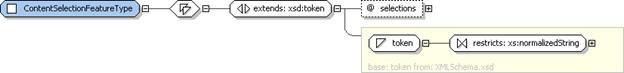
Figure 96:
ContentSelectionFeatureType structure.
The ContentSelectionFeatureType
allows for the definition of the number of times a feature can be referenced if
that feature includes a Multiplicity
element.
For example, a software package has a server
and client; the server can be deployed only on one machine, but the client can
be deployed on multiple machines and configured to reference the one server.
The server, for performance reasons, is limited to 10 client connections. To
limit the number of times the client can be deployed, the selections attribute should be set to “10”.
4.12.14.1 ContentSelectionFeatureType
Property Summary
|
Name
|
Type
|
*
|
Description
|
|
|
[extends]
xsd:token
|
|
See
the xsd:token definition in [XSD].
|
|
selections
|
VariableExpressionType
|
0..1
|
The
number of times a feature with Multiplicity in the referenced package should
be deployed.
|
4.12.14.2 ContentSelectionFeatureType
Property Usage Notes
See the xsd:token definition in [XSD] for inherited attributes and elements.
§
selections:
The value of selections MUST be, or resolve to, a
positive integer that is within the bounds of the minSelections and maxSelections
attributes defined in the Multiplicity
element of the referenced feature.
See the VariableExpressionType
section for structure and additional usage details [4.6.1].
Figure 97: MultiSelectType structure.
MultiSelectType
defines a way to associate features with a defined minimum and maximum number
of selections allowed. A MultiSelect
element MAY be used to support identification of mutually exclusive features.
4.12.15.1 MultiSelectType
Property Summary
|
Name
|
Type
|
*
|
Description
|
|
Feature
|
FeatureReferenceType
|
2..*
|
A
reference to a feature in the list of features defined in the MultiSelect
element.
|
|
minSelections
|
xsd:nonNegativeInteger
|
0..1
|
Minimum
number of features that must be selected.
**default
value=“0”
|
|
maxSelections
|
xsd:positiveInteger
|
0..1
|
Maximum
number of features that can be selected.
|
4.12.15.2 MultiSelectType
Property Usage Notes
§
Feature:
The value MUST reference the id of a feature
element.
See
the FeatureReferenceType section for
structure and additional usage details [4.12.8].
§
minSelections,
maxSelections: When it is not necessary that any of the features in the MultiSelect list be selected, the
default of “0” can be used.
Mutually exclusive features can be defined
using a MultiSelect element with two
features, minSelections set to “0”
and maxSelections set to “1”.
If multiple instances of a single feature
are selected via multiplicity, the set of multiple instances count only once
toward the minimum and maximum. In other words, the count is based solely on
the features selected, not on how many instances of each feature are selected.
When maxSelections
is not defined, all of the features in the MultiSelect
MAY be selected for a particular deployment.
If defined, the maxSelections value MUST be greater than or equal to the minSelections value and MUST be less than
or equal to the number of referenced features.
Localization refers to enabling a particular
piece of software to support one or more languages. Anything that needs to be
deployed to provide support for a particular language in that software is
considered localization content. Translated materials are a primary, but not
the only, example of localization content.
Localization content is similar in many ways
to other content, but there are important differences in how localization
content is selected for deployment that lead to the need for a separate content
hierarchy and separate types. Two criteria determine whether or not localization
content is in scope for a particular deployment:
§
The first criterion has to do with the language
or languages supported by the localization content. At least one of the
languages must be in scope for the content to be selected.
§
The second criterion has to do with the
availability of the resources to be localized–the localization base. The
localization base may be a resource deployed by base or selectable content, or
it may be a resource previously deployed and found in the deployment
environment.
The types described in this section support
definition of metadata describing the criteria for determining when
localization content is in scope.
Figure 98:
LocalizationContentType structure.
The LocalizationContent
tree contains all content created specifically to provide localization by
deploying language-specific materials for a particular location. The
localization support provided can be for content defined in the SDD or it can
be for resources in the deployment environment that are not created or modified
by deployment of the SDD. Each element defined in the LocalizationContent hierarchy is in scope for a particular
deployment when it supports a language that is in scope for that deployment and
when its localization base, if any, is available.
4.13.1.1 LocalizationContentType
Property Summary
|
Name
|
Type
|
*
|
Description
|
|
LocalizationUnit
|
LocalizationUnitType
|
0..*
|
Contains
artifacts that create, modify or delete language support.
|
|
ContainedLocalizationPackage
|
ReferencedPackageType
|
0..*
|
Identifies
an SDD whose contents are aggregated to create, modify or delete language
support.
|
|
CompositeLocalizationUnit
|
CompositeLocalizationUnitType
|
0..*
|
An
organizational element that groups localization content and defines metadata
common to all the grouped content.
|
4.13.1.2 LocalizationContentType
Property Usage Notes
§
LocalizationUnit:
When there is no need to group a LocalizationUnit
with other units that have common metadata, the LocalizationUnit is defined at the top level of the hierarchy. A LocalizationUnit defined at the top level
of the LocalizationContent hierarchy
is in scope for a particular deployment when its Condition and LocalizationBase,
if any, evaluate to true and its Languages
element, if any, defines a language that is in scope for the deployment.
See
the LocalizationUnitType section for
structure and additional usage details [4.13.2].
§
ContainedLocalizationPackage:
ContainedLocalizationPackage
definitions include a list of languages supported by the contained package. The
package need not be processed if none of those languages is in scope for a
particular deployment.
See
the ReferencedPackageType section for
structure and additional usage details [4.10.1].
§
CompositeLocalizationUnit:
CompositeLocalizationUnit is a
construct that allows organization of localization content in a way that is
meaningful to the SDD author.
One example use of a CompositeLocalizationUnit is to group a set of LocalizationUnits that provide support for a variety of languages
for the same resource. This eliminates the need to define identical LocalizationBase elements in every LocalizationUnit. It can be defined once
in the CompositeLocalizationUnit.
If evaluation of the CompositeLocalizationUnit's Condition,
Languages and LocalizationBase determines that it is not selected for deployment,
none of the content elements defined below it in the hierarchy are selected.
Requirements, Variables, Conditions and
Completion elements common to all
child content elements MAY be defined once in the CompositeLocalizationUnit rather than once in each nested element.
See
the CompositeLocalizationUnitType
section for structure and additional usage details [4.13.3].
Figure 99: LocalizationUnitType
structure.
The LocalizationUnit
element defines artifacts that deploy localization content for one group of
resources whose translations are packaged together. Localization content
consists of materials that have been translated into one or more languages.
4.13.2.1 LocalizationUnitType
Property Summary
|
Name
|
Type
|
*
|
Description
|
|
Identity
|
IdentityType
|
0..1
|
Human-understandable
identity information about the LocalizationUnit.
|
|
Condition
|
ConditionType
|
0..1
|
A
condition that determines if the content element is relevant to a particular
deployment.
|
|
Variables
|
VariablesType
|
0..1
|
Variables
that can be referenced in the LocalizationUnit’s requirement and artifact
definitions.
|
|
RequiredBase
|
RequiredBaseType
|
0..1
|
A
resource that will be updated when the LocalizationUnit’s UpdateArtifact is
processed.
|
|
Requirements
|
RequirementsType
|
0..1
|
Requirements
that must be met prior to successful processing of the LocalizationUnit’s
artifacts.
|
|
Languages
|
LanguagesType
|
0..1
|
The
LocalizationUnit’s artifacts contain materials translated into these
languages.
|
|
Completion
|
CompletionType
|
0..*
|
Describes
completion actions such as restart and the conditions under which the action
is applied.
|
|
LocalizationBase
|
RequiredBaseType
|
0..1
|
A
resource whose translatable characteristics will be localized by processing
the LocalizationUnit’s InstallArtifact.
|
|
ResultingResource
|
ResultingResourceType
|
0..*
|
A
resource that will be installed or updated by processing the
LocalizationUnit’s artifacts.
|
|
Artifacts
|
InstallationArtifactsType
|
1
|
The
set of artifacts associated with the LocalizationUnit.
|
|
|
xsd:any
|
0..*
|
|
|
id
|
xsd:ID
|
1
|
An
identifier for the LocalizationUnit scoped to the deployment descriptor.
|
|
targetResourceRef
|
xsd:IDREF
|
1
|
Reference
to the resource that can process the LocalizationUnit’s artifacts.
|
|
|
xsd:anyAttribute
|
0..*
|
|
4.13.2.2 LocalizationUnitType
Property Usage Notes
§
Identity:
The Identity element defines
human-understandable information that reflects the identity of the provided
localization resources as understood by the end user of the solution. Identity has elements that are common
with elements in the corresponding PackageDescriptor’s
PackageIdentity element, for example,
Name and Version. The values of these common elements SHOULD be the same as
the corresponding PackageIdentity
element values.
See the IdentityType
section for structure and additional usage details [3.4].
§
Condition:
A Condition is used when the LocalizationUnit’s content should be
deployed only when certain conditions exist in the deployment environment.
For example, for a package that has one
artifact that should be processed when the operating system is Linux and
another artifact that should be processed when the operating system is Windows,
the LocalizationUnit defining metadata
for the Linux artifact would have a condition on the operating system being
Linux. The LocalizationUnit defining
metadata for the Windows artifact would have a condition on the operating
system being Windows.
Conditions
should not be used to identify the resource that will be localized by the LocalizationUnit. The LocalizationBase element is used for
that purpose. A LocalizationUnit can
have both a Condition and a LocalizationBase.
See the ConditionType
section for structure and additional usage details [4.5.1].
§
Variables:
A Variables element defines variables
that can be used in the definition of requirements and artifact parameters.
When
the deployment descriptor defines a single LocalizationUnit
at the top level, that is, not inside a CompositeInstallable,
the variables it defines can also be referred to in any element under Topology.
See
the VariablesType section for
structure and additional usage details [4.6.3].
§
RequiredBase:
RequiredBase identifies the resource
that must exist prior to applying the LocalizationUnit’s
update artifact.
See the RequiredBaseType
section for structure and additional usage details [4.7.8].
§
Requirements:
Requirements MUST be met prior to processing
the LocalizationUnit’s artifacts.
See the RequirementsType
section for structure and additional usage details [4.7.1].
§
Languages:
Languages lists the languages of the
translated material deployed by the LocalizationUnit.
See the LanguagesType
section for structure and additional usage details [4.13.6].
§
Completion:
A Completion element MUST be included
if the artifact being processed requires a system operation such as a reboot or
logoff to occur to function successfully after deployment or if the artifact
executes a system operation to complete deployment of the contents of the
artifact.
There MUST be an artifact associated with the
operation defined by a Completion
element.
For example, if there is a Completion element for the install operation, the LocalizationUnit must define an InstallArtifact.
See the CompletionType
section for structure and additional usage details [4.3.14].
§
LocalizationBase:
LocalizationBase identifies the
resource or resources that can be localized by processing the LocalizationUnit. A resource that
satisfies the constraints defined in the LocalizationBase
is one that can be localized by applying the LocalizationUnit.
If no resource is found that meets the
constraints defined in LocalizationBase
during a particular deployment, then the LocalizationUnit
is not considered to be in scope for that deployment. This does not represent
an error.
Translations created or modified by the LocalizationUnit are for human-readable
text included with the LocalizationBase
resources.
See the RequiredBaseType
section for structure and additional usage details [4.7.8].
§
ResultingResource:
The ResultingResources for a LocalizationUnit MUST NOT identify resources other than
localization resources.
See the ResultingResourceType
section for structure and additional usage details [4.8.1].
§
Artifacts:
When the LocalizationUnit is a singleton
defined outside of a CompositeInstallable,
it MUST define at least one artifact element and MAY define one of each type of
artifact element allowed for its type. The inclusion of an artifact element in
a singleton LocalizationUnit implies
support for the associated operation.
When the LocalizationUnit
is defined within a CompositeInstallable,
it MUST define exactly one artifact. The artifact defined MAY be any artifact
allowed in a LocalizationUnit and it
MUST support the single top level operation
defined by the CompositeInstallable.
This does not mean the operation associated with the artifact has to be the
same as the one defined by the CompositeInstallable.
For example, an install of a localization
resource may be required during the update of the overall solution, in which
case the LocalizationUnit would
define an InstallArtifact to support
the top level update operation.
See the InstallationArtifactsType
section for structure and additional usage details [4.3.4].
§
id: The
id attribute may be useful to
software that processes the SDD, for example, for use in creating log and trace
messages.
§
targetResourceRef:
The targetResourceRef attribute MUST
reference the id of a resource
element in Topology that will process
the LocalizationUnit’s artifacts to
create or modify the localization resources identified in the LocalizationUnit’s ResultingResource elements.
Figure 100:
CompositeLocalizationUnitType structure
CompositeLocalizationUnitType
provides the type definition for all CompositeLocalizationUnit
elements in the LocalizationContent
hierarchy. CompositeLocalizationUnit
elements define nested localization content elements and metadata that applies
to all of the nested elements.
4.13.3.1 CompositeLocalizationUnitType
Property Summary
|
Name
|
Type
|
*
|
Description
|
|
Identity
|
IdentityType
|
0..1
|
Human-understandable identity information about
the CompositeLocalizationUnit.
|
|
Condition
|
ConditionType
|
0..1
|
A condition that determines if the CompositeLocalizationUnit
is relevant to a particular deployment.
|
|
Variables
|
VariablesType
|
0..1
|
Variables for use within the
CompositeLocalizationUnit and content elements nested beneath it in the
hierarchy.
|
|
RequiredBase
|
RequiredBaseType
|
0..1
|
A resource that will be updated when the nested
elements are processed.
|
|
Requirements
|
RequirementsType
|
0..1
|
Requirements that must be met prior to successful
processing of the nested content elements.
|
|
Languages
|
LanguagesType
|
0..1
|
Localization elements defined within CompositeLocalizationUnit
contain materials translated into these languages.
|
|
Completion
|
CompletionType
|
0..*
|
Describes
completion actions such as restart and the conditions under which the action
is applied.
|
|
LocalizationBase
|
RequiredBaseType
|
0..1
|
A resource whose translatable characteristics
will be localized by processing the nested content elements.
|
|
ResultingResource
|
ResultingResourceType
|
0..*
|
A localization resource that will be installed or
updated by processing the nested content elements.
|
|
LocalizationUnit
|
LocalizationUnitType
|
0..*
|
Contains artifacts that will create, modify or
delete language support.
|
|
ContainedLocalizationPackage
|
ReferencedPackageType
|
0..*
|
Identifies an SDD whose contents are aggregated
to create, modify or delete language support.
|
|
CompositeLocalizationUnit
|
CompositeLocalizationUnitType
|
0..*
|
An organizational element that groups
localization content and defines metadata common to all the grouped content.
|
|
|
xsd:any
|
0..*
|
|
|
id
|
xsd:ID
|
1
|
An identifier for the CompositeLocalizationUnit that
is unique within the deployment descriptor.
|
|
|
xsd:anyAttribute
|
0..*
|
|
4.13.3.2 CompositeLocalizationUnitType
Property Usage Notes
§
Identity:
The CompositeLocalizationUnit, like
all content elements, is a unit of packaging. Its identity is the identity of a
unit of packaging and may be useful to package management tools. The identity
MAY be similar or identical to the identity of the ResultingResource(s).
See
the IdentityType section for
structure and additional usage details [3.4].
§
Condition:
If the composite and the elements nested beneath it are applicable only in
certain environments, a Condition can
be defined. When the Condition is not
met, the composite and its nested elements are not in scope.
See
the ConditionType section for structure
and additional usage details [4.5.1].
§
Variables:
Variables used by more than one
nested element can be defined in the CompositeLocalizationUnit
for efficiency both in composing and processing the SDD. Variables are visible to all nested content elements.
See
the VariablesType section for
structure and additional usage details [4.6.3].
§
RequiredBase:
If the processing of all the update artifacts in the nested content elements
results in a single resource being updated, that resource can be defined in the
CompositeLocalizationUnit’s RequiredBase element.
See
the RequiredBaseType section for
structure and additional usage details [4.7.8].
§
Requirements:
When a CompositeLocalizationUnit is
in scope for a particular deployment–as determined by evaluation of its LocalizationBase and Languages properties–then its
requirements MUST be met.
See
the RequirementsType section for
structure and additional usage details [4.7.1].
§
Languages:
The Languages element in the CompositeLocalizationUnit MUST NOT be
defined or MUST define the union of all languages supported by the nested
content elements. For nested content elements to be evaluated to determine if
they are in scope, the CompositeLocalizationUnit
must be in scope. When Languages is
present in the CompositeLocalizationUnit,
it must define one of the languages in scope for the particular deployment if
any of the nested elements are to be evaluated. If Languages is not present in a CompositeLocalizationUnit,
evaluation of all the child elements still is required, as long as the other
elements of CompositeLocalizationUnit
have evaluated to true. When the Languages
and/or the LocalizationBase element
in a CompositeLocalizationUnit is not
defined, the nested content elements must be evaluated to determine if they are
in scope.
See the LanguagesType
section for structure and additional usage details [4.13.6].
§
Completion:
When a particular completion action applies to all nested elements and should
be performed only once for the entire group, it can be defined in the CompositeLocalizationUnit rather than in
each individual element.
See
the CompletionType section for
structure and additional usage details [4.3.14].
§
LocalizationBase:
A LocalizationBase element evaluates
to true when the resource identified in the base is created by a content
element that is in scope for the deployment or it already exists in the
deployment environment.
When
the LocalizationBase is defined it
must evaluate to true for any of the nested content elements to be evaluated.
If it evaluates to false, none of the nested content elements are in scope. If
it evaluates to true, the nested content elements may be in scope.
When
the LocalizationBase and/or the Languages element in a CompositeLocalizationUnit is not
defined, the nested content elements must be evaluated to determine if they are
in scope.
See
the RequiredBaseType section for
structure and additional usage details [4.7.8].
§
ResultingResource:
If there are one or more resources that will be created when the nested content
elements are processed, they can be defined here.
See
the ResultingResourceType section for
structure and additional usage details [4.8.1].
§
LocalizationUnit:
LocalizationUnits defined within the
composite typically have common metadata. Metadata defined in the composite
does not need to be repeated in the nested element. Definitions in the nested LocalizationUnit are additions to those
defined in the composite.
See
the LocalizationUnitType section for
structure and additional usage details [4.13.2].
§
ContainedLocalizationPackage:
A ContainedLocalizationPackage is
defined in a CompositeLocalizationUnit
for the same reasons that a LocalizationUnit
is–because it has metadata in common with other elements defined in the
composite.
See the ReferencedPackageType
section for structure and additional usage details [4.10.1].
§
CompositeLocalizationUnit:
A CompositeLocalizationUnit can be
nested inside another CompositeLocalizationUnit
when some of the metadata is shared only by a subset of the elements nested in
the higher level composite.
For example, the higher level composite
might contain operating system requirements that apply to all localization
content and nested composites might group localization content by localization
base.
§
id: This
id is not referred to by any other
element in the deployment descriptor.
The id
attribute may be useful to software that processes the SDD, for example, for
use in creating log and trace messages. It also may be useful for associating
custom discovery logic with the CompositeLocalizationUnit’s
resource-related elements.
Figure 101:
LanguageSelectionsType structure.
LanguageSelectionsType
provides the type definition for the Languages
element in CompositeInstallable that describes
the languages supported by the SDD as a whole. It also provides the type
definition for the Languages element
in features that allows a feature to override the SDD-wide definitions.
4.13.4.1 LanguageSelectionsType
Property Summary
|
Name
|
Type
|
*
|
Description
|
|
Mandatory
|
LanguagesType
|
0..1
|
The
set of languages that will be deployed.
|
|
Optional
|
OptionalLanguagesType
|
0..1
|
The
set of language selections available to the deployer.
|
4.13.4.2 LanguageSelectionsType
Property Usage Notes
§
Mandatory:
The deployer has no ability to determine if a mandatory language will be
deployed.
See
the LanguagesType section for
structure and additional usage details [4.13.6].
§
Optional:
Each language group in the list of optional languages defines a list of one or
more languages that can be selected together.
Language
groups defined in LanguageSelections
MAY be used to allow the deployer to select individual languages or to allow
selection of multiple languages as a single choice.
See
the OptionalLanguagesType section for
structure and additional usage details [4.13.5].
Figure 102: OptionalLanguagesType
structure
OptionalLanguagesType
supports definition of a language or sets of languages that the deployer can
optionally choose for deployment. This type is used to define the global set of
optional languages in CompositeInstallable
as well as any Feature-specific set that
overrides the global set for a particular Feature.
4.13.5.1 OptionalLanguagesType
Property Summary
|
Name
|
Type
|
*
|
Description
|
|
Language
|
LanguageType
|
1..*
|
A
single language that can be chosen individually.
|
|
LanguageSet
|
LanguageSetType
|
1..*
|
A
set of languages that can be chosen together.
|
4.13.5.2 OptionalLanguagesType
Property Usage Notes
§
Language:
When the SDD author allows the deployer to individually select a language for
deployment, it is defined in a Language
element within OptionalLanguages.
See
the LanguageType section for
structure and usage details [4.13.7].
§
LanguageSet:
When the SDD author allows the deployer to select languages for deployment as a
set, it is defined in a LanguageSet
element within OptionalLanguages.
One example of a reason to define optional
languages in a set rather than individually is for a group of languages that
are packaged together and whose deployment cannot be separated.
See the LanguageSetType
section for structure and additional usage details [4.13.8].
Figure 103: LanguagesType
structure.
LanguagesType
supports expression of a list of languages. It is used in the Languages elements of content elements
to list languages supported by that content element. It is also used as the
type of the Mandatory element that
lists languages that are deployed by default.
4.13.6.1 LanguagesType
Property Summary
|
Name
|
Type
|
*
|
Description
|
|
Language
|
LanguageType
|
1..*
|
A
single language definition.
|
4.13.6.2 LanguagesType
Property Usage Notes
§
Language:
Each language definition MAY include display information as well as the
language code that identifies the language.
See
the LanguageType section for
structure and additional usage details [4.13.7].
Figure 104: LanguageType
structure.
LanguageType
supports the definition of display information and the language code for one
language. It is used everywhere a language is defined in the SDD.
4.13.7.1 LanguageType
Property Summary
|
Name
|
Type
|
*
|
Description
|
|
DisplayName
|
DisplayTextType
|
0..1
|
A
name for the language.
|
|
Description
|
DisplayTextType
|
0..1
|
A
description of the language.
|
|
ShortDescription
|
DisplayTextType
|
0..1
|
A
short description of the language.
|
|
type
|
xsd:language
|
1
|
The
locale code for the language.
|
4.13.7.2 LanguageType
Property Usage Notes
§
DisplayName:
This element MAY be used to provide human-understandable
information. If used, it MUST provide a label for the language.
See the DisplayElementGroup
section for structure and additional usage details [4.14.2].
§
Description,
ShortDescription: These elements MAY be used to provide
human-understandable information. If used, they MUST provide a description
of the language.
The
Description element MUST be defined
if the ShortDescription element is
defined.
See
the DisplayElementGroup section for
structure and additional usage details [4.14.2].
§
type:
The type attribute MUST be defined as
a value that conforms to the set of language codes defined by [RFC3066].
For example, “de” is a locale code for
German and “en-US” is the locale code for English in the United States.

Figure 105: LanguageSetType
structure.
LanguageSetType
provides the type definition for the
OptionalLanguages elements of CompositeInstallable
and Feature. It defines a set of
languages that can be selected together.
4.13.8.1 LanguageSetType
Property Summary
|
Name
|
Type
|
*
|
Description
|
|
DisplayName
|
DisplayTextType
|
0..1
|
A
name for the set of languages.
|
|
Description
|
DisplayTextType
|
0..1
|
A
description of the set of languages.
|
|
ShortDescription
|
DisplayTextType
|
0..1
|
A
short description of the set of languages.
|
|
Language
|
LanguageType
|
1..*
|
A
set of one or more language codes.
|
4.13.8.2 LanguageSetType
Property Usage Notes
§
DisplayName:
This element MAY be used to provide human-understandable
information. If used, it MUST provide a label for the set of languages.
For example, “Eastern European Languages” or
“French, English and German”.
See the DisplayElementGroup
section for structure and additional usage details [4.14.2].
§
Description,
ShortDescription: These elements MAY be used to provide
human-understandable information. If used, they MUST provide a description
of the set of languages.
The
Description element MUST be defined
if the ShortDescription element is
defined.
See
the DisplayElementGroup section for
structure and additional usage details [4.14.2].
§
Language:
The languages defined in this element MUST be selected together.
See
the LanguageType section for structure
and additional usage details [4.13.7].
4.14 Display Information
There are many places throughout the SDD
where translatable information intended for display to humans MAY be defined. All
display information definitions can include a translationKey that can be used as an index into a file containing
translations.
Figure 106: DescriptionGroup
structure.
The DescriptionGroup
type is used throughout the SDD to provide human-readable, translatable,
descriptive-text elements.
4.14.1.1 DescriptionGroup
Property Usage Notes
§
Description:
This is a description of the defining element unless usage notes for that
element state otherwise. It can be as long as necessary to provide a useful
description.
The
Description element MUST be defined
if the ShortDescription element is
defined.
See
the DisplayTextType section for
details about associating this text with translated text [4.14.3].
§
ShortDescription:
This is a short description of the defining element unless usage notes for that
element state that it refers to something else. It SHOULD provide a limited
description that can be used by tools where limited text is allowed, for
example, fly-over help.
See the DisplayTextType
section for details about associating this text with translated text [4.14.3].

Figure 107: DisplayElementGroup
structure.
The DisplayElementGroup
is used throughout the package descriptor and deployment descriptor to provide
human-readable, translatable names, descriptions and/or short descriptions for
a variety of elements.
4.14.2.1 DisplayElementGroup
Property Usage Notes
§
DisplayName:
This is a label for the defining element unless usage notes for that element
state otherwise.
See the DisplayTextType
section for details about associating this text with translated text [4.14.3].
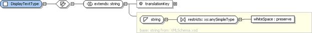
Figure 108: DisplayTextType
Structure.
Elements of DisplayTextType define translatable strings and an optional key to
translated text in language bundle files. DisplayTextType
extends the xsd:string
type with an optional translationKey
attribute.
4.14.3.1 DisplayTextType
Property Usage Notes
§
translationKey: The translationKey
attribute is a value that can be used as an index into a file containing
translations of DisplayTextType
elements in the DeploymentDescriptor
and/or PackageDescriptor. The value
of the translationKey MUST match an
entry in the message bundle referenced by the descriptorLanguageBundle attribute in the package descriptor.
An implementation
MAY claim conformance to the entirety of the SDD specification (including all
conformance levels) or one or more particular conformance levels, and/or one or
more particular profiles (SDD conformance levels and profiles are detailed
next).
An SDD conformance
level (CL) is defined, consistent with [CONFORM], as a
subset of the schema intended to enable a certain set of capabilities to be
achieved, based on SDDs that restrict their content to the particular CL. The
purpose of conformance levels is to allow subsets of the full set of
capabilities that can be expressed using an SDD to be implemented. The proper
subsets are expected to be easier to implement, but still offer features, value
and interoperability that make it worthwhile to implement a particular CL in
certain circumstances.
SDD conformance
levels are designated as CL1 and CL2. CL1 is a proper subset of the schema; CL2
represents the full schema. CL1 is the minimal set or core of the specification
that shall be implemented by all products. CL2 includes all of CL1 and consists
of the entire specification.
The following
sections describe the defined CLs for SDD.
Table 1 expresses the capabilities for each defined CL.
|
|
Conformance Level 1
|
Conformance Level 2
|
|
Description
|
Single target, simple package.
|
Multi-target, aggregated packages; full
deployment capabilities with all functions enabled by the SDD schema.
|
|
Objective
|
Serve as the “on-ramp” for SDD adoption.
Deploy pre-prepared content that needs limited customization (basic
parameters). Descriptors serve as contract between assembly and operations.
Exemplary use case is “wrappering” existing packages in SDD.
|
Serve as the expected level for
newly-authored non-legacy SDDs. Deploy newly-prepared content that has
related components in a solution, with various topologies. Most robust
specification (and corresponding run-time implementations) of SDD. Exemplary
use case is non-trivial, non-legacy solution deployment.
|
|
Included Schema Functions
|
·
Solution
package with single component (singleton IU, CU, or LU; no composite) and single
target topology
·
Solution
package dependency checking for given environment
·
base
installations and maintenance
·
Simple
uninstall (based on information in single descriptor)
·
Ability
to deploy existing artifact formats appropriate for the target environment
·
Some
localization possible (localization of the units that are supplied)
|
All
functions, including:
·
Aggregation
(composites)
·
Features
·
Selectable
features
·
Conditional
content
·
Variable-target
topology
·
Robust
localization
|
|
Excluded Functions
|
·
Features
·
Selectable
content
·
Requisites
·
Aggregation
·
Multi-target
topology
·
Robust
localization
·
Replacements
and modifications that change base resource/solution composition
(including obsolescence)
·
Backwards
compatibility, range enforcement
·
Verification
of installation and configuration
|
None
|
Table 1: SDD
conformance level capabilities summary.
CL1
SDDs can be used to describe the inputs, requirements and results of processing
a single deployment artifact. This artifact could be one that deploys, updates,
configures or localizes software resources. This is useful for simple
deployments that require only a single artifact. CL2 SDDs add support for
aggregation of multiple artifacts and SDDs into solutions; definition of features
that optionally select content; and requisite software that can be deployed if
needed to satisfy requirements. CL1 SDDs can be aggregated by CL2 SDDs.
For
example, CL2 SDDs can describe a solution that consists of a Web server, an
application server, a database and one or more applications, in which each of
these components is described by its own individual SDD and an aggregating CL2
SDD aggregates them into the composite solution.
The differences between CL1 and CL2 that are
summarized in Table 1 are detailed next. These make use of the information
that is in the SDD schema; see [CL1_Schema] for the CL1 schema files, and [CL2_Schema] for the CL2 schema files. The differences between
the CL1 and CL2 schema files are isolated to the “sdd-dd” namespace. The
“sdd-common” and “sdd-pd” namespaces contain identical schema files for each
namespace with respect to CL1 and CL2.
5.2.2.1 Type
Definitions Modified in CL2
A few SDD types
used in CL1 have additional elements added in CL2. The types listed in the left
column of Table 2 exist in both CL1 and CL2 with different definitions.
The elements in the right column are the sub-elements added to the type
definitions in CL2.
|
Type Name
|
CL2 Sub-Element Names
|
|
DeploymentDescriptorType
|
Requisites
CompositeInstallable
|
|
InstallationArtifactsType
|
RepairArtifact
|
|
ResultingResourceType
|
Relationship
|
|
ResultingChangeType
|
Relationship
|
|
ResourceConstraintGroup
|
UniquenessConstraint
RelationshipConstraint
|
|
ConditionalResourceConstraintType
|
UniquenessConstraint
RelationshipConstraint
|
|
RequirementType
|
Dependency
|
|
AlternativeRequirementType
|
Dependency
|
Table 2. Modified Types.
Several SDD types
have altered structure between CL1 and CL2. The types listed in the left column
of Table 3 are valid for both CL1 and CL2; however, valid
structure for these types differs between CL1 and CL2, as shown in the center
and right columns.
|
Type
|
CL1 Structure
|
CL2 Structure
|
|
DeploymentDescriptorType
|
Choice of one of
the following: InstallableUnit, ConfigurationUnit, or LocalizationUnit
|
Choice of one of
the following: InstallableUnit, ConfigurationUnit, or LocalizationUnit;
or one or more
CompositeInstallable elements
|
|
RequirementType
|
Sequence of ResourceConstraint elements
|
Unbounded choice
of ResourceConstraint elements and Dependency elements
|
|
AlternativeRequirementType
|
Sequence of ResourceConstraint elements
|
Unbounded choice
of ResourceConstraint elements and Dependency elements
|
Table 3.
Altered types in CL2.
As seen in Table 2, CL2 adds two new elements to DeploymentDescriptor.
The CompositeInstallable element provides the definition of an aggregate
deployment. CompositeInstallable is a complex element with many
sub-elements. The second element added to DeploymentDescriptor is Requisites.
Requisites is a list of references to SDDs that can be used, if needed,
to satisfy deployment requirements defined in the CompositeInstallable.
Table 4 includes the CL2 types that are introduced in support
CompositeInstallable and Requisites
|
BaseContentType
|
FeatureType
|
PackageFeatureReferenceType
|
|
CompositeInstallableType
|
GroupsType
|
ReferencedPackageType
|
|
CompositeLocalizationType
|
GroupType
|
RelationshipConstraintType
|
|
CompositeUnitType
|
InternalDependencyType
|
RelationshipType
|
|
ConstrainedResourceType
|
LanguageSelectionType
|
RequiredContentSelectionType
|
|
ContentElementReferenceType
|
LocalizationContentType
|
RequisitesType
|
|
ContentListGroup
|
MultiplicityConstraintType
|
ResourceMapType
|
|
ContentSelectionFeatureType
|
MultiplicityType
|
ResultingChangeMapType
|
|
DependencyType
|
MultiSelectType
|
ResultingResourceMapType
|
|
FeatureReferenceType
|
NestedFeatureType
|
SelectableContentType
|
|
FeaturesType
|
OptionalLanguagesType
|
UniquenessConstraintType
|
Table 4 SDD types introduced in CL2.
One SDD type has an
additional enumeration value that is valid only for CL2-based implementations.
The type listed in the left column of Table
5 is valid for both CL1 and CL2; however, the value in
the right column is valid only for CL2.
|
Type
|
CL2 Enumeration Value
|
|
OperationType
|
repair
|
Table 5 Extended
enumeration value in CL2.
Profiles are
intended to specify detailed information that can be used in an SDD to promote
interoperability. An SDD profile is defined consistent with [CONFORM], to
identify the functionality, parameters, options and/or implementation
requirements necessary to satisfy the requirements of a particular community of
users. SDD profiles are intended to enable a specific set of use cases,
typically in a particular domain. Profiles are considered largely orthogonal to
CLs; whereas a CL is a subset of the schema, a profile specifies the usage of
the schema, including appropriate conventions and content values, to accomplish
a particular set of use cases (typically in a particular domain).
A starter profile is initially defined
with version 1.0 of this specification and is published separately. This starter
profile defines terms and patterns that can be used to generate other specific
profiles and addresses the content values that are required to support the SDD
XML examples that also are published separately.
The starter profile
is not intended to be a complete vocabulary for all SDDs, but rather to
illustrate the format and provide example content so that additional profiles
can be generated in the future. The starter profile leverages and extends the
CIM standard [CIM] for many content values, but other profiles MAY
use other content values.
Other profiles MAY be
published by the TC in the future, and new profiles can be created as specified
in 5.3.1.
An implementation
MAY claim conformance to one or more particular profiles.
The SDD TC has
created a starter profile as described in 5.3. The SDD TC MAY create additional profiles in the
future.
Others MAY create
SDD profiles for use cases, domains, or user communities that are not addressed
by the currently available profiles from the SDD TC. When creating new
profiles, it is RECOMMENDED that profile creators follow the model of the starter
profile and any existing profiles and reuse content from existing standards
where possible. It is also RECOMMENDED that implementations publish the
profile(s) that they support.
The SDD TC publishes
the starter profile and MAY publish any other profiles created by the SDD TC.
Profiles created by
the SDD TC SHALL be made available by the SDD TC.
Profiles created by
others MAY be published and made available by those parties and/or submitted to
the SDD TC for consideration for publication by the SDD TC, according to the
OASIS policies and procedures, including intellectual property rights. The SDD
TC MAY publish and make available the new profiles through majority vote of the
TC.
Profiles are
applicable to particular usage models, domains and/or user communities. An
implementation MAY claim conformance to one or more particular profiles.
Versions of the specification
use the version value defined in the schemaVersion attribute described
in section 3.2. New versions of the specification MAY update the
conformance level contents.
Profiles also use
the schemaVersion attribute described in section 3.2. New versions of profiles MAY update the profile
contents.
Minor version
updates of the schema, specification and profiles SHALL be backward-compatible
with proceeding major versions (for example, all “1.x” versions are
backward-compatible with version “1.0”).
Moreover, minor
version updates of the schema, specification and profiles SHALL be
backward-compatible with proceeding minor versions of the same major version
(for example, version “1.4” is backward-compatible with versions “1.3”, “1.2”,
“1.1” and “1.0”).
Major version
updates of the schema, specification and profiles are NOT REQUIRED to be
backward-compatible with previous versions and MAY NOT be backward-compatible
with previous versions. For example, if non-backward-compatible changes occur
in version “1.x”, the new version is “2.0”. Although new major versions MAY
have substantial backward compatibility, backward compatibility is not
guaranteed for all aspects of the schema across major versions.
An SDD conforms to
this specification if it conforms to the SDD schema and follows the syntax and
semantics defined in the normative portions of this specification. An SDD MAY
conform to conformance levels CL1 or CL2.
An implementation
conforms to this specification if it conforms to, at minimum, conformance level
CL1 of the SDD schema; supports at least one SDD profile; and follows the
syntax and semantics defined in the normative portions of this specification.
An implementation MAY support conformance levels CL1 or CL2 and MAY support
additional SDD profiles.
This section is the
conformance claim for how this document conforms to [CONFORM]. The
conformance issues in section 8 of [CONFORM] apply to
this document as follows:
1. This
document is applicable to SDDs as defined in this specification. To claim
conformance to this document, all the requirements in section 5.5.1 SHALL be met.
2. This
document MAY be implemented in its entirety or in defined conformance levels
CL1 and CL2. This document does not define profiles, but the SDD TC MAY define
profiles that MAY be implemented.
3. This
document allows extensions. Each
implementation SHALL fully support all required functionality of the
specification exactly as specified. The use of extensions SHALL NOT contradict
nor cause the non-conformance of functionality defined in the specification.
4. This
document contains no discretionary items.
5. This
document’s normative language is English. Translation into other languages is
permitted.
The SDD schema is implemented by multiple schema files.
Types defined in each file are identified by a specific namespace prefix, as
indicated in the following list:
§
cd04-sdd-common-1.0.xsd (prefix: sdd-common)
Contains definitions of common types used in the SDD
specification, including identity and fix-identity types, UUID and version
types, and the display text type.
http://docs.oasis-open.org/sdd/v1.0/cd04/CL1Schema/cd04-sdd-common-1.0.xsd
http://docs.oasis-open.org/sdd/v1.0/cd04/FullSchema/cd04-sdd-common-1.0.xsd
§
cd04-sdd-deploymentDescriptor-1.0.xsd (prefix: sdd-dd)
Contains the deployment descriptor specification,
including various content types.
http://docs.oasis-open.org/sdd/v1.0cd04/CL1Schema/cd04-sdd-deploymentDescriptor-1.0.xsd
http://docs.oasis-open.org/sdd/v1.0/cd04/FullSchema/cd04-sdd-deploymentDescriptor-1.0.xsd
§
cd04-sdd-packageDescriptor-1.0.xsd (prefix: sdd-pd)
Contains the package descriptor specification,
including types related to packages and files.
http://docs.oasis-open.org/sdd/v1.0/cd04/CL1Schema/cd04-sdd-packageDescriptor-1.0.xsd
http://docs.oasis-open.org/sdd/v1.0/cd04/FullSchema/cd04-sdd-packageDescriptor-1.0.xsd
Example SDDs showing the use of the schema can be found at the
following address.
http://docs.oasis-open.org/sdd/v1.0/sdd-examples-v1.0.zip
The following individuals have participated in the creation
of this specification and are gratefully acknowledged:
Participants:
Dr. Howard Abrams, CA
Mr. Joshua Allen, Macrovision Corporation
Mr. Rich Aquino, Macrovision Corporation
Mr. Lazar Borissov, SAP AG
Ms. Debra Danielson, CA
Mr. Robert DeMason, SAS Institute, Inc.
Mr. Robert Dickau, Macrovision Corporation
Mr. Quenio dos Santos, Macrovision Corporation
Mrs. Christine Draper, IBM
Mr. Adrian Dunston, SAS Institute, Inc.
Mr. James Falkner, Sun Microsystems
Mr. Keisuke Fukui, Fujitsu Limited
Mr. Randy George, IBM
Mr. Nico Groh, SAP AG
Mr. Frank Heine, SAP AG
Ms. Merri Jensen, SAS Institute, Inc.
Dr. Hiro Kishimoto, Fujitsu Limited
Mr. Thomas Klink, SAP AG
Mr. Jason Losh, SAS Institute, Inc.
Ms. Julia McCarthy, IBM
Mr. Art Middlekauff, Macrovision Corporation
Mr. Brent Miller, IBM
Mr. Ed Overton, SAS Institute, Inc.
Mr. Chris Robsahm, SAP AG
Dr. David Snelling, Fujitsu Limited
Mr. Thomas Studwell, Dell
Dr. Weijia (John) Zhang, Dell