Functional Elements Specification
Committee Draft 2.0,
Document identifier:
fwsi-fe-2.0-guidelines-spec-cd-01.doc
Location:
http://www.oasis-open.org/apps/org/workgroup/fwsi/documents.php
Editor:
Contributor(s):
Andy Tan, Individual (andytan@intrinix.net)
Shawn Cheng Hua-Shan, XMLBoss (shawn@xmlboss.net)
Kenneth Lim, Crimson Logic Pte Ltd (kennethlim@crimsonlogic.com)
Viren Baraiya, Crimson Logic Pte Ltd (viren@crimsonlogic.com)
Jagdip Talla, Crimson Logic Pte Ltd (jagdip@crimsonlogic.com)
Roberto Pascual, Infocomm Development Authority (IDA) of
Lee Eng Wah, SIMTech (ewlee@simtech.a-star.edu.sg)
V.Ramasamy, SIMTech (rama@simtech.a-star.edu.sg)
Abstract:
The ability to
provide robust implementations is a very important aspect to create high
quality Web Service-enabled applications and to accelerate the adoption of Web
Services. The Framework for Web Services Implementation (F
This document specifies a set of Functional Elements for practitioners to instantiate into a technical architecture, and should be read in conjunction with the Functional Elements Requirements document. It is the purpose of this specification to define the right level of abstraction for these Functional Elements and to specify the purpose and scope of each Functional Element so as to facilitate efficient and effective implementation of Web Services.
Status:
This document is updated periodically on no particular schedule.
Committee members should send comments on this specification to the fwsi-fesc@lists.oasis-open.org list. Others should subscribe to and send comments to the fwsi-comment@lists.oasis-open.org list. To subscribe, send an email message to fwsi-comment-request@lists.oasis-open.org with the word "subscribe" as the body of the message.
For information on
whether any patents[1]
have been disclosed that may be essential to implementing this specification,
and any offers of patent licensing terms, please refer to the Intellectual
Property Rights section of the F
Table of Contents
2.1 Data
Integrator Functional Element (new)
2.1.5 Related
Technologies and Standards
2.2 Error
Management Functional Element (new)
2.2.5 Related
Technologies and Standards
2.3 Event
Handler Functional Element
2.3.5 Related
Technologies and Standards
2.4 Group
Management Functional Element
2.4.5 Related
Technologies and Standards
2.5 Identity Management Functional Element
2.5.5 Related Technologies and Standards
2.6 Information Catalogue Functional Element (new)
2.6.5 Related
Technologies and Standards
2.7 Information
Reporting Functional Element (new)
2.7.5 Related
Technologies and Standards
2.8 Key
Management Functional Element (new)
2.8.5 Related
Technologies and Standards
2.9 Log Utility
Functional Element
2.9.5 Related
Technologies and Standards
2.10 Notification
Functional Element
2.10.5 Related
Technologies and Standards
2.11 Phase and
Lifecycle Management Functional Element
2.11.5 Related
Technologies and Standards
2.12 Policy
Management Functional Element (new)
2.12.5 Related Technologies
and Standards
2.13 Policy
Enforcement Functional Element (new)
2.13.5 Related
Technologies and Standards
2.14 Presentation
Transformer Functional Element (Deprecated)
2.15 QoS Functional Element (new)
2.15.5 Related
Technologies and Standards
2.16 Role and
Access Management Functional Element
2.16.5 Related
Technologies and Standards
2.17 Search
Functional Element
2.17.5 Related
Technologies and Standards
2.18 Secure
SOAP Management Functional Element
2.18.5 Related
Technologies and Standards
2.19 Sensory
Functional Element
2.19.5 Related
Technologies and Standards
2.20 Service
Level Management Functional Element (new)
2.20.5 Related
Technologies and Standards
2.21 Service
Level Enforcement Functional Element (new)
2.21.5 Related
Technologies and Standards
2.22 Service
Management Functional Element
2.22.5 Related
Technologies and Standards
2.23 Service
Registry Functional Element
2.23.5 Related
Technologies and Standards
2.24 Service
Router Functional Element (new)
2.24.5 Related
Technologies and Standards
2.25 Service
Tester Functional Element (Deprecated)
2.26 Transformer Functional Element (new)
2.26.5 Related
Technologies and Standards
2.27 User
Management Functional Element
2.27.5 Related
Technologies and Standards
2.28 Web
Service Aggregator Functional Element
2.28.5 Related
Technologies and Standards
3 Functional
Elements Usage Scenarios
3.3 Decoupled
User Access Management
3.4 Single-Sign-On
for Distributed Services (Applications)
The purpose of OASIS Framework for Web Services
Implementation (F
One of the F
The target audiences for this document are expected to be solution providers who intend to use the Functional Elements Specification to create building blocks that can be instantiated into the technical architecture of their solutions or software vendors and independent software vendors (ISVs) that are expected to build the functional elements specified into their products. Individuals and researchers who are interested in Web Services will also be able to benefit from this document. It is recommended that this document should be used in tandem with the Functional Elements Requirements document, to ensure that readers have a holistic view to the thought processes and knowledge that are encapsulated.
1.1 Document Outline
This document describes the Functional Elements in three main sections. In this section, explanation on the motivation for creating this Specification and the kind of impact that it will create for Web Service-enabled implementations and the terminology used in the normative part of this document are included.
Section 2 lists the identified Functional Elements arising from requirements documented in the Functional Elements Requirements document [[2]]. Under each of the ensuing FE, the following descriptions are provided:
·
Motivation
A section for providing a short
introduction explaining the motivation of including the FE from an application
Point-Of-View, including cross-referencing of the requirements for the
Functional Element
·
Terms Used
A glossary of the terms used. An explanation or illustration of the runtime capabilities of the Functional Element are also provided where appropriate.
·
Key Features
A list of key features to be
implemented is provided here and is expressed in the normative form.
·
Interdependencies
In this section, the
interdependencies between Functional Elements are provided to clarify the
linkages between
·
Related Technologies and Standards
Here, the reliance of the Functional Elements on related technologies and specifications (or standards) are provided
Section 3 provides the examples of how the Functional Elements can be assembled to accelerate web service-enabled applications. From these Functional Elements, a variety of solutions can be built.
1.2 Motivation
In a Service-Oriented Architecture (SOA) environment, new applications/services are created through the assembly of existing services. One of the key advantages of this loosely coupled model is that it allows the new application/service to leverage on 3rd party services. As a typical 3rd party’s implementation of the services is done via the software component approach, this specification further proliferate new applications/services by defining a framework for Web Services implementation consisting of Functional Elements. Through these Functional Elements, which are implementation neutral, this Specification hopes to influence future software development towards assembly of services rather than ‘pure built only’.
1.3 Terminology
Within this document the key words “MUST”, “MUST NOT”, “REQUIRED”, “SHALL”, “SHALL NOT”, “SHOULD”, “SHOULD NOT”, “RECOMMENDED”, “MAY”, and “OPTIONAL” in this document are to be interpreted as described in RFC2119 [[3]].
Cross-references to the Functional Elements Requirements document [2] are designated throughout this specification to the requirement contained where the requirement number is enclosed in square brackets (e.g. [MANAGEMENT-005]).
2.1 Data Integrator Functional Element (new)
2.1.1 Motivation
The Data Integrator Functional element is expected to be used for enabling easy and simple mechanisms to access disparate data sources by
:
Providing unified data view of enterprise across various data sources
,
Enabling the partitioned view of data for different groups/departments based on defined logical views, and
Performing data processing or transformation before presenting the defined logical data view(s).
This
Functional Element fulfills the following requirements from the Functional
Elements Requirements Document 02:
Primary Requirements
1.1 PROCESS-220
to PROCESS-236.
Secondary
Requirements
1.2 None
2.1.2 Terms Used
|
Terms |
Description |
|
Batch
Retrieval Definition |
Batch retrieval definition defines how batch data retrieval is performed. The definition of batch retrieval would include the XML schema for the XML format of retrieved data, the mapping of the data fields in the format to the data fields in the logical data view and the schedule of batch retrieval |
|
Data
Repository |
Data repository is a form of persistent data storage used by Data
Integrator to store information of logical data views information. |
|
Data
Source |
Data source is physical data storage where data can be retrieved. It
may include relational database, XML database, LDAP, text file, XML file, URL
that pointing to a set of data in Internet. |
|
Data
Transformation Rule |
Data transformation rule defines how raw data is
transformed into the data format that is requested by final presentation. Data transformation rule has two types. –The first type is the one that applies at the
logical data view level and generates instances of data for the whole data
view. » An example of this type rule could be a name of the
pre-defined function that gets data instances from various data sources and
fills in the data view. –The second type is the one that applies at the data
field level of the logical data view and only generates the data for that
particular data field. » An examples of this type rule could be a formula
like: data field 1 in logical data view = data field 1 in data source 1 X data field 2 in data source 2 . |
|
Logical
Data View |
Logical data view is a conceptual/semantic data model. It is defined by the name of logical data view, owner, created date, the data fields, the sources of data fields, the constraints of data view, and the transformation rule associated. |
|
|
|||
|
Figure 1: An Overview of the Data Integrator Functional Element |
Figure 1 depicts the basic concepts of how
the participating entities collaborate together in the Data Integrator
Functional Element. Data can be physically scattered across various
data sources, residing on the local area network (LAN) or over Wide Area
Network (WAN). Examples include RDBMS, XML database, XML files, URLs that point
to a set of data in the Internet, etc. Data Integrator enables the creation of
different set of logical data views for various applications or systems. Users
of Data Integrator manipulate the data according to the logical data view
defined through a unified access interface. Logical data views could be
physically stored in Data Repository for easy and fast access.
2.1.3 Key Features
Implementations
of the Data Integrator Functional Element are expected to provide the following
key features:
1.
The
Functional Element MUST provide the capability to manage the available data
sources. This includes capability to:
1.1. Add new data source to the pool of
available data sources.
1.2.
Remove
data source from the pool of available data sources.
The Functional Element MUST provide the capability to define a logical data view based on the pool of available data sources
1. .
The Functional Element MUST provide capability to manage the updating and deletion of a logical data view
2. .
The Functional Element MUST provide capability to manage the creation, updating and deletion of data transformation rules
3. .
The Functional Element MUST provide capability to retrieve data based on the logical data view defined
4. .
The Functional Element MUST provide a unified way to query data based on defined logical data views
5. .
The Functional Element MUST provide a mechanism to extract data from various data sources and transform the data according to defined transformation rules for a logical data view
6. .
In addition, the following key features could be provided to enhance the Functional Element further:
1. The Functional Element MAY provide capability to insert, update and delete data based on a logical data view (where applicable).
2. The Functional Element MAY provide the capability to retrieve batch data based on logical data view according to a schedule and present the retrieved data in predefined XML formats.
3. The Functional Element MAY provide the capability to manage the definition of batch data retrieval. This includes capability to:
3.1 Define a batch data retrieval
3.2 Disable the schedule of batch data retrieval
3.3 Enable the schedule of batch data retrieval
3.4 Remove the definition of batch data retrieval
4. 5 The Functional Element MAY implement data repository to host consolidated data. This data repository hosts the physical entity that stores the content of a logical data view.
5. 6 The Functional Element MAY provide a mechanism to synchronize data between data repository and data sources if data repository is provided.
2.1.4 Interdependencies
None
2.1.5 Related Technologies and Standards
RDBMS, LDAP, XML Database
2.1.6 Model
|
|
|||
|
Figure 2: Model Of the Data Integrator Functional Element |
2.1.7 Usage Scenarios
2.1.7.1 Manage data sources
2.1.7.1.1 Description
This
use case allows the user to manage the available data sources on which logical
data views are created.
2.1.7.1.2 Flow of Events
2.1.7.1.2.1 Basic Flow
The use case begins when
the user of the Data Integrator wants to add in new data sources or remove
existing data sources.
1: The user sends a
request to Data Integrator together with data source profile and operation.
2: Based on the
operation it specified, one of the following sub-flows is executed:
If the operation is ‘Add in data source’, then sub-flow 2.1 is executed.
If the operation is ‘Remove data source’, then sub-flow 2.2 is executed.
2.1:
Add in data source.
2.1.1: The Functional Element gets the data source profile data, i.e. name, description, data source location for connection, login Id and password of the user who has privileges to manipulate data sources.
2.1.2: The Functional Element registers the data source as available data source.
2.2:
Remove data source.
2.2.1: The Functional Element gets the name of data sources
2.2.2: The Functional Element checks whether the data source is valid data source.
2.2.3: The Functional Element removes the data source from the pool of available data source (with the assumption that the user has a valid login Id and password).
3: The Functional
Element returns the results to indicate the success or failure of this
operation to the user and the use case ends.
2.1.7.1.2.2 Alternative Flows
1: Data Source Already
Registered.
1.1: If in the basic flow 2.1.2, the data source is already registered, Functional Element will return an error message to the user and the use case ends.
2: Data Source Not
Exist.
2.1: If in the basic flow 2.2.2, the data source is not registered as available data source, Functional Element will return an error message to the user and the use case ends.
3: Persistency Mechanism
Error.
3.1: If in the basic flow 2.1 and 2.2, the Functional Element cannot perform data persistency, Functional Element will return an error message to the user and the use case ends.
2.1.7.1.3 Special Requirements
None.
2.1.7.1.4 Pre-Conditions
None.
2.1.7.1.5 Post-Conditions
None.
2.1.7.2 Manage Data Views
2.1.7.2.1 Description
This
use case allows the user to manage the logical data views.
2.1.7.2.2 Flow of Events
2.1.7.2.2.1 Basic Flow
The use case begins when
the user wants to create/retrieve/update/delete a logical data view.
1: The user sends
request to manage logical data view together with logical data view definition
and operation.
2: Based on the
operation it specifies, one of the following sub-flows is executed:
If the operation is ‘Create Data View’, the sub-flow 2.1 is executed.
If the operation is ‘Retrieve Data View’, the sub-flow 2.2 is executed.
If the operation is ‘Update Data View’, the sub-flow 2.3 is executed.
If the operation is ‘Delete Data View’, the sub-flow 2.4 is executed.
2.1:
Create Data View.
2.1.1: The Functional Element gets logical data view definition, i.e. name, description, owner of data view, created date, data fields of data view, the source fields of data fields, and transformation rule.
2.1.2: The Functional Element checks whether the logical data view exists.
2.1.3: The Functional Element creates the logical data view exists.
2.2:
Retrieve Data View.
2.2.1: The Functional Element gets name of the logical data view and retrieve condition.
2.2.2: The Functional Element retrieves the logical data view’s information according to the condition.
2.3:
Update Data View.
2.3.1: The Functional Element gets name of the logical data view and its definition
2.3.2: The Functional Element checks whether the logical data view exists.
2.3.3: The Functional Element updates the logical data view definition
2.4:
Delete Data View.
2.4.1: The Functional Element gets name of the logical data view.
2.4.2: The Functional Element checks whether the logical data view exists.
2.4.3: The Functional Element removes the logical data view.
3: The Functional
Element returns the results of the operation to the user and the use case ends.
2.1.7.2.2.2 Alternative Flows
1: Data View Already
Exists.
1.1: If in the basic flow 2.1.2, the data view is already defined, Functional Element returns an error message and the use case ends.
2: Data View Cannot Be
Deleted.
2.1: If in the basic flow 2.4.3, the data of the logical data view is stored in Data Repository, Functional Element returns an error message and the use case ends.
3: Data View Not Found.
3.1: If in the basic flow 2.2.2, 2.3.2 and 2.4.2, the data view does not exist, Functional Element will return an error message and the use case ends.
4: Data View Cannot Be
Updated.
4.1: If in the basic flow 2.4.3, the data of
the logical data view is stored in Data Repository, Functional Element returns
an error message and the use case ends.
5: Persistency Mechanism
Error.
5.1: If in the basic flow 2.1.2, 2.1.3, 2.2, 2.3.2, 2.3.3, 2.4.2 and 2.4.3, the Functional Element cannot perform data persistency, Functional Element will return an error message to the user and the use case ends.
2.1.7.2.3 Special Requirements
None.
2.1.7.2.4 Pre-Conditions
None.
2.1.7.2.5 Post-Conditions
None.
2.1.7.3 Manage Transformation Rules
2.1.7.3.1 Description
This
use case allows the user to manage the data transformation rules that are used
by the Data Integrator to perform the data transformation before passing data
back to users.
2.1.7.3.2 Flow of Events
2.1.7.3.2.1 Basic Flow
The use case begins when
the user wants to create/retrieve/update/delete a data transformation
rule.
1: The user sends
request to manage data transformation rule together with the definition of
transformation rule and operation.
2: Based on the
operation it specifies, one of the following sub-flows is executed:
If the operation is ‘Define Data Transformation Rule’, the sub-flow 2.1 is executed.
If the operation is ‘Retrieve Data Transformation Rule’, the sub-flow 2.2 is executed.
If the operation is ‘Update Data Transformation Rule’, the sub-flow 2.3 is executed.
If the operation is ‘Delete Data Transformation Rule’, the sub-flow 2.4 is executed.
2.1:
Create Data Transformation Rule.
2.1.1: The Functional Element gets the definition of the data transformation rule, i.e. name, description, rule type, function name, data view name, and applied data fields.
2.1.2: The Functional Element checks whether the data transformation rule exists.
2.1.3: The Functional Element creates the data transformation rule.
2.2:
Retrieve Data Transformation Rule.
2.2.1: The Functional Element gets name of the data transformation rule and retrieve condition.
2.2.2: The Functional Element retrieves the data transformation rule’s information according to the condition.
2.3:
Update Data Transformation Rule.
2.3.1: The Functional Element gets the name of data transformation rule.
2.3.2: The Functional Element checks whether data transformation rule exists.
2.3.3: The Functional Element updates the
definition of the data transformation rule.
2.4:
Delete Data Transformation Rule.
2.4.1: The Functional Element gets the name of data transformation rule.
2.4.2: The Functional Element checks whether the data transformation rule exists.
2.4.3: The Functional Element removes the
data transformation rule from the Functional Element
3: The Functional
Element returns the results of the operation to the user and the use case ends.
2.1.7.3.2.2 Alternative Flows
1: Data Transformation
Rule Already Exists.
1.1: If in the basic flow 2.1.2, the data transformation rule is already defined, Functional Element returns an error message and the use case ends.
2: Data Transformation
Rule Cannot Be Deleted.
2.1: If in the basic flow 2.4.3, the data of the logical data view, on which the data transformation rule is applied, is stored in Data Repository, Functional Element returns an error message and the use case ends.
3: Data Transformation
Rule Not Found.
3.1: If in the basic flow 2.2.2, 2.3.2 and
2.4.2, the data transformation rule does not exist, Functional Element will
return an error message and the use case ends
4: Data Transformation
Rule Cannot Be Updated.
4.1: If in the basic flow 2.3.3, the data of
the logical data view, on which the data transformation rule is applied, is
stored in Data Repository, Functional Element returns an error message and the
use case ends.
5: Logical Data View Not
Exist.
4.1: If in the basic flow 2.1.3, the data of
the logical data view, on which the data transformation rule is applied, dose
not exist, Functional Element returns an error message and the use case ends.
6: Persistency Mechanism
Error.
5.1: If in the basic flow 2.1.2, 2.1.3, 2.2,
2.3.2, 2.3.3, 2.4.2 and 2.4.3, the Functional Element cannot perform data
persistency, Functional Element will return an error message to the user and
the use case ends.
2.1.7.3.3 Special Requirements
None.
2.1.7.3.4 Pre-Conditions
None.
2.1.7.3.5 Post-Conditions
None.
2.1.7.4 Manage Batch Data Extraction
2.1.7.4.1 Description
This
use case allows the user to define and disable the batch data extraction.
2.1.7.4.2 Flow of Events
2.1.7.4.2.1 Basic Flow
The use case begins when
the user wants to define, remove, enable and disable a batch data extraction.
1: The user sends
request to manage batch data extraction together with the definition of batch
data extraction and operation.
2: Based on the
operation it specifies, one of the following sub-flows is executed:
If the operation is ‘Define Batch Data Extraction’, the sub-flow 2.1 is executed.
If the operation is ‘Remove Batch Data Extraction Definition’, the sub-flow 2.1 is executed.
If the operation is ‘Enable Batch Data Extraction’, the sub-flow 2.2 is executed.
If the operation is ‘Disable Batch Data Extraction’, the sub-flow 2.3 is executed.
2.1:
Define Batch Data Extraction.
2.1.1: The Functional Element gets batch data extraction definition, i.e. name, description, XML schema for the XML data format, the mapping of data fields from logical data view to XML data file, and extraction schedule.
2.1.2: The Functional Element checks whether the batch data extraction exists.
2.1.3: The Functional Element creates the batch data extraction.
2.2:
Remove Batch Data Extraction Definition.
2.2.1: The Functional Element gets name of the batch data extraction.
2.2.2: The Functional Element checks whether the batch data extraction exists.
2.2.3: The Functional Element removes the
batch data extraction from the Functional
Element.
2.3:
Enable Batch Data Extraction.
2.3.1: The Functional Element gets name of the batch data extraction.
2.3.2: The Functional Element checks whether the batch data extraction exists.
2.3.3: The Functional Element enables the
batch data extraction.
2.4:
Disable Batch Data Extraction.
2.4.1: The Functional Element gets name of the batch data extraction.
2.4.2: The Functional Element checks whether the batch data extraction exists.
2.4.3: The Functional Element disables the
batch data extraction.
3: The Functional
Element returns the results of the operation to the user and the use case ends.
2.1.7.4.2.2 Alternative Flows
1: Batch Data Extraction
Exist.
1.1: If in the basic flow 2.1.2, the batch data extraction is already defined, Functional Element returns an error message and the use case ends.
2: Batch Data Extraction
Not Found.
2.1: If in the basic flow 2.2.3, 2.3.3 and
2.4.3, the batch data extraction does not exist, Functional Element will return
an error message and the use case ends
3: Persistency Mechanism
Error.
3.1: If in the basic flow 2.1.2, 2.1.3,
2.2.2, 2.2.3,2.3.2, 2.3.3, 2.4.2 and 2.4.3, the Functional Element cannot
perform data persistency, Functional Element will return an error message to
the user and the use case ends.
2.1.7.4.3 Special Requirements
None.
2.1.7.4.4 Pre-Conditions
None.
2.1.7.4.5 Post-Conditions
None.
2.1.7.5 Retrieve Data
2.1.7.5.1 Description
This
use case allows the user to perform data retrieval based on the logical data
view defined.
2.1.7.5.2 Flow of Events
2.1.7.5.2.1 Basic Flow
The use case begins when
the user wants to perform data retrieval based on a logical data view.
1: The user sends request to retrieve data by providing the name of logical data view and SQL query statement.
2: The Functional Element checks whether the logical data view exists.
3: The Functional Element retrieves the definition of logical data view specified.
4: The Functional Element verifies the correctness of the SQL statement by checking the syntax of statement and the data fields used.
5: The Functional Element retrieves the definition of data transformation rule related with the data view.
6: The Functional Element performs the data retrieval from data sources
7: The Functional Element performs the data transformation to the data retrieved and fill up the data according to the definition of the logical data view.
8: The Functional
Element returns the results of the operation to the user and the use case ends.
2.1.7.5.2.2 Alternative Flows
1: Query Statement Is
Invalid.
1.1: If in the basic flow 4, the SQL
statement is not valid, Functional Element returns an error message and the use
case ends.
2: Data View Not Found.
2.1: If in the basic flow 3, the specified
data view is not found, Functional Element returns an error message and the use
case ends.
3: Data Source Not
Available.
3.1: If in the basic flow 6, the data sources
are not available for retrieving data, Functional Element returns an error
message and the use case ends.
4: Data Transformation
Rule Not Found.
4.1: If in the basic flow 5, the data
transformation rule is not available, Functional Element returns an error
message and the use case ends.
5: Data Repository Are
Not Available.
5.1: If in the basic flow 6, the data of the
logical data view is stored in Data Repository and the Data Repository is not
available, Functional Element returns an error message and the use case ends.
2.1.7.5.3 Special Requirements
None.
2.1.7.5.4 Pre-Conditions
None.
2.1.7.5.5 Post-Conditions
None.
2.1.7.6 Manipulate Data
2.1.7.6.1 Description
This
use case allows the user to insert, update, and delete data based on a logical
data view defined.
2.1.7.6.2 Flow of Events
2.1.7.6.2.1 Basic Flow
The use case begins when
the user wants to insert, update, and delete data based on a logical data
view.
1: The user sends
request to manipulate data by providing the name of the logical data view and
SQL statement.
3: The Functional Element retrieves the definition of logical data view specified.
4: The Functional Element verifies the correctness of the SQL statement by checking the syntax of statement and the data fields used.
5: The Functional Element checks the violation of operations based on the definition of logical data view.
6: The Functional Element performs the operation specified in SQL statement.
7: The Functional
Element returns the results of the operation to the user and the use case ends.
2.1.7.6.2.2 Alternative Flows
1: Manipulation
Statement Is Invalid.
1.1: If in the basic flow 4, the SQL
statement is not valid, Functional Element returns an error message and the use
case ends.
2: Data View Not Found.
2.1: If in the basic flow 3, the specified
data view is not found, Functional Element returns an error message and the use
case ends.
3: Data Source Are Not
Available.
3.1: If in the basic flow 6, the data sources
are not available for retrieving data, Functional Element returns an error
message and the use case ends.
4: SQL Error.
4.1: If in the basic flow 6, there is any error
of SQL statement execution, Functional Element returns an error message and the
use case ends.
2.1.7.6.3 Special Requirements
None.
2.1.7.6.4 Pre-Conditions
None.
2.1.7.6.5 Post-Conditions
None.
2.1.7.7 Extract Data in Batch
2.1.7.7.1 Description
This
use case allows the user to perform batch data retrieval in a scheduled
approach based on a logical data view defined.
2.1.7.7.2 Flow of Events
2.1.7.7.2.1 Basic Flow
The use case begins when
the user wants to perform batch data retrieval or the time is up for scheduled
batch data retrieval.
1: The user sends request
to retrieve data by providing the name of the batch data retrieval or the
Functional Element clock generates a trigger.
2: The Functional Element retrieves the definition of batch data retrieval according to the name.
3: The Functional Element prepares the parameters for invocation of Retrieve data use case
4: The Functional Element invokes the Data Retrieve use case
5: The Functional Element formats the data according to the format defined in the batch data retrieval definition
6: The Functional Element
returns the results of the operation to the user and the use case ends.
2.1.7.7.2.2 Alternative Flows
1: Definition of Batch
Data Retrieval Not Found.
1.1: If in the basic flow 2, the definition
of batch data retrieval is not found, Functional Element returns an error
message and the use case ends.
2: Error Returned From
Data Retrieve Use Case.
2.1: If in the basic flow 4, the use case
Retrieve data returns an error, Functional Element returns an error message and
the use case ends.
2.1.7.7.3 Special Requirements
None.
2.1.7.7.4 Pre-Conditions
None.
2.1.7.7.5 Post-Conditions
None.
2.1.7.8 Manage Data Repository
2.1.7.8.1 Description
This
use case allows the user to manage data repository.
2.1.7.8.2 Flow of Events
2.1.7.8.2.1 Basic Flow
The use case begins when
the user wants to persistent a logical data view in the data repository, or the
user wants to dispose the persistency of a data view from the data
repository.
1: The user sends
request to manage data repository by providing the name of the logical data
view.
2: Based on the
operation it specifies, one of the following sub-flows is executed:
If the operation is ‘Persistent Data View’, the sub-flow 2.1 is executed.
If the operation is ‘Dispose Data View’, the sub-flow 2.1 is executed.
2.1: Persistent Data View
2.1.1: The Functional Element retrieves the definition of the logical data view.
2.1.2: The Functional Element forms the SQL statement according to the definition of the logical data view.
2.1.3: The Functional Element performs the data retrieval from data sources.
2.1.4: The Functional Element performs the data transformation according to the transformation rule.
2.1.5:
The Functional Element creates table in Data Repository and fill in the table
with data generated in previous step.
2.2:
Dispose Data View
2.1.1: The Functional Element forms the SQL statements of deleting the table
2.1.3: The Functional Element deletes the table in Data Repository.
3: The Functional
Element returns the results of the operation to the user and the use case ends.
2.1.7.8.2.2 Alternative Flows
1: Data View Not Found
1.1: If in the basic flow 2.1.1, the
definition of batch data retrieval is not found, Functional Element returns an
error message and the use case ends.
2: Data Exist
2.1: If in the basic flow 2.1.3, there is
data in the table, Functional Element returns an error message and the use case
ends.
3: Data Repository Error
3.1: If in the basic flow 2.1.5 and 2.2.3,
there is an error in Data Repository, Functional Element returns an error
message and the use case ends.
4: Data Source Not
Available
4.1: If in the basic flow 2.1.3, the data sources
related is not available, Functional Element returns an error message and the
use case ends
2.1.7.8.3 Special Requirements
None.
2.1.7.8.4 Pre-Conditions
None.
2.1.7.8.5 Post-Conditions
None.
2.1.7.9 Synchronize Data
2.1.7.9.1 Description
This
use case allows the user to synchronize data in Data Repository with the data
from data sources.
2.1.7.9.2 Flow of Events
2.1.7.9.2.1 Basic Flow
The use case begins when
the user wants to synchronize data of a logical data view in data repository
with the data in data sources, or the time is up for synchronization of
data.
1: The user sends
request to synchronize data repository or the Functional Element clock
generates a trigger.
2: The Functional
Element gets or finds those data views that are required to be synchronized
with data sources.
3: The Functional
Element retrieves data view definitions.
4: The Functional
Element retrieves data from data sources according th definition of logical
data view.
5: The Functional
Element performs the data transformation on the data retrieved.
6: The Functional
Element update the table in Data Repository with the data generated in previous
step.
7: The Functional
Element returns the result of the operation and the use case ends.
2.1.7.9.2.2 Alternative Flows
1: Data View Definition
Not Found
1.1: If in the basic flow 3, the definition
of batch data retrieval is not found, Functional Element returns an error
message and the use case ends.
2: Data Repository Error
2.1: If in the basic flow 6, there is an
error in updating the Data repository, Functional Element returns an error
message and the use case ends.
3: Data Source Not
Available
3.1: If in the basic flow 4, the data sources
related is not available, Functional Element returns an error message and the
use case ends
2.1.7.9.3 Special Requirements
None.
2.1.7.9.4 Pre-Conditions
None.
2.1.7.9.5 Post-Conditions
None.
2.2 Error Management Functional Element (new)
2.2.1 Motivation
Error
management is an important aspect in any software application development. In particular, it is important to know the
cause of error in the Service Oriented Architecture (SOA) environment as an
application can consume any service provided from any domain space spans across
the Internet space. When an error
occurs, it can be from within the same application domain or from different
domain space. Hence, it is important to
know the system state when the error occurred in the SOA environment. For example, when an error occurred, what
services were used; which services’ interfaces were used; the passed in
parameters and its associated values used for the interfaces, the time when the
error occurred, API or SOAP invocation, etc are the important information for
managing the application in the SOA environment.
The
Error Management Functional Element is a framework designed to capture the
system state at which the error occurred.
The variables that governed the system state when an error occurred are
defined as follows:
·
The time
at which the error occurred.
·
The
class/object name that the error occurred.
·
The
method name of the said class/object at which the error occurred.
·
The
input parameters, parameters types and its associated values of the said method
at which the error occurred.
·
The
expected output type of the mentioned method name.
·
The
error category, error code and error severity assigned by the application.
·
The name
of the consumed service/component.
·
The name
of the interface used for the said service/component.
·
The
input parameters and types defined for the said interface.
·
The
values used for the mentioned input parameters.
·
The
Universal Resource Location (URL) of the consumed service endpoint.
·
The SOAP
Fault message <Fault> element
returned from the consumed service.
·
The type
of invocation whether it is a Web Service call or Application Programming
Interfaces (APIs) call.
·
The
domain controller information includes :
o
Name of
the domain controller
o
Contact
Information, .e. Email Id, Short Message Services (SMS), Telephone, Mobile
phone, etc.
o
Means of
Notification
The
main motivation of the Functional Element is to provide a snapshot and capture
all the system state information for an application when an error
occurred. It assists system
administrator to manage the system fault better for the necessary actions
required for tracking the fault.
Figure
3 illustrates the perspective usage of Error Management Functional
Element. When an error occurred in an
application, the Functional Element will be used to capture the system state
into a data store which can either be a database or a flat file.
|
|
|
Figure 3: Error Management Functional Element
Usage |

This Functional Element fulfills the following requirements from the Functional Elements Requirements:
Primary Requirements
·
MANAGEMENT-340 to MANAGEMENT-346
2.2.2 Terms Used
|
Terms |
Description |
|
Error Category |
The Category
or classification of error. For example, the category of error can be
classified as: Database
error à DATABX, Transaction
error à TRANSX, Authentication
error à AUTHEX, System error
à SYSTEMX, Application-specific
error à APPLSX, Third-party
service error à THIRDPX, etc. |
|
Error Code |
The Error Code defined for each Error Category. For example, 001, 002, 003, etc |
|
Error Severity |
The Error Severity defined for each Error
Code. For example, the severity could be in the order of Critical, Major, Minor, Warning, For Information Only. |
|
External Application Error |
The External Application Error is defined as an error / fault / exception occurred by consuming external Web Services / Components providers. For example, customized exception, SOAPException and SOAP Fault resulted from APIs or SOAP invocation to external components or Web Services. |
|
Internal Application Error |
The Internal Application Error is defined as error / fault / exception raised resulted from an internal processing or run time error. For example, exceptions such as Null Pointer Exception, Class Type Casting, Array Out of Bound, etc. that occurred due to processing or run time error. |
Figure 4 is an example illustrating the error hierarchy in terms of
Error Category, Error Code and Error Severity.
|
|
|
Figure 4: An Example of Error Hierarchy |
For example, a database could give rise to a number of errors. For example, database not found, invalid
username and password, no data found, null field, duplicate key etc are the
common database errors. Each database
error could have different severity. For
example, database not found or invalid username and password are critical to
business logic. An illustration of the
resultant error code is defined as DATABX0001-CRITICAL.
2.2.3 Key Features
Implementations of the Error Management Functional Element are expected to provide the following key features:
1. The Functional Element MUST provide the ability to create new Error Category.
2. The Functional Element MUST provide the ability to modify and delete defined Error Category.
3. The Functional Element MUST provide the ability to all the information stored in the Error Category. This includes the capability to:
3.1 Add new Error Code(s) and descriptions into a Error Category
3.2 Retrieve, modify and delete error code and descriptions
3.3 Support Error Code(s) in numeric, alpha-numeric or string format
4. The Functional Element MUST provide a mechanism to capture the defined system state at which an error occurred.
In addition, the following key features could be provided to enhance the Functional Element further:
1. The Functional Element MAY provide the ability to manage Error Severity by enabling the capability to:
1.1. Tag/Add to Error Code defined,
1.2. Retrieve, modify and delete Severity tag to Error Code, and
1.3. Retrieve information based on either Error Code or Severity.
2.2.4 Interdependencies
|
Direct Dependency |
|
|
Log Utility Functional Element |
The Log Utility Functional Element helps to log the audit trial. |
|
Notification Functional Element |
The Notification Element helps to notify the target user via email, or short messaging service. |
2.2.5 Related Technologies and Standards
|
Specifications |
Specific References |
|
XML Version 1.0 |
Extensible Markup Language (XML) 1.0 (Third
Edition) W3C Recommendation |
|
XML Schema |
XML
Schema Part 0: Primer Second Edition W3C Recommendation XML
Schema Part 1: Structures Second Edition W3C Recommendation XML
Schema Part 2: Datatypes Second Edition W3C Recommendation |
|
|
Web Services Description Language ( |
|
SOAP Version 1.1 |
Simple Object Access Protocol (SOAP) 1.1
W3C Note |
|
Functional Elements Specification |
OASIS Functional Elements Specification Committee Specifications 1.0, |
2.2.6 Model
|
|
|
Figure 5: Model Of the Error Management Functional Element |
2.2.7 Usage Scenarios
2.2.7.1 Manage Error Category
2.2.7.1.1 Description
This use case allows the error management administrator to manage Error Category.
2.2.7.1.2 Flow of Events
2.2.7.1.2.1 Basic Flow
The use case begins when the user wants to create/retrieve/update/delete an Error Category.
1: The user sends a request to manipulate an Error Category.
2: Based on the operation it specifies, one of the following sub-flows is executed:
If the operation is ‘Create Error Category’, the sub-flow 2.1 is executed.
If the operation is ‘Retrieve Error Category’, the sub-flow 2.2 is executed.
If the operation is ‘Update Error Category’, the sub-flow 2.3 is executed.
If the operation is ‘Delete Error Category’, the sub-flow 2.4 is executed.
2.1: Create Error Category.
2.1.1: The Functional Element gets category definition.
2.1.2: The Functional Element checks whether the category exists.
2.1.3: The Functional Element creates the category and save it in the error database.
2.2: Retrieve Error Category.
2.2.1: The Functional Element gets the Error Category name.
2.2.2: The Functional Element checks whether the category exists.
2.2.3: The Functional Element retrieves the Error Category’s information from the Error Management Data sources.
2.3: Update Error Category.
2.3.1: The Functional Element gets the Error Category name.
2.3.2: The Functional Element checks whether the Error Category exists.
2.3.3: The Functional Element updates the category definition and save it in the Error Management Data sources.
2.4: Delete Error Category.
2.4.1: The Functional Element gets the Error Category name.
2.4.2: The Functional Element checks whether the Error Category name exists.
2.4.3: The Functional Element checks whether the Error Code associated to the Error Category name exists.
· If Error Codes associated to the Error Category name exists, then basic sub-flow 2.4.4 is executed.
· If Error Codes associated to the Error Category name does not exist, then the basic sub-flow 2.4.7 is executed.
2.4.4: Error Codes associated to the Error Category name exists.
· If the Error Severity associated to the respective Error Codes exists, the basic sub-flow 2.4.5 is executed.
· If the Error Severity associated to the respective Error Code does not exist, then the basic sub-slow 2.4.6 is executed.
2.4.5: The Error Severity Exist.
2.4.5.1: The Functional Element removes the error severities associated to the respective Error Code from sub-flow 2.4.4.
2.4.6: The Error Severity Does Not Exist.
2.4.6.1 The Functional Element removes the respective Error Codes from sub-flow 2.4.3 from the Error Management Data sources.
2.4.7: The Error Codes Associated to the Error Category Name Does Not Exist.
2.4.7.1: The Functional Element removes the respective Error Codes associated to the Error Category name (from sub-flow 2.4.3) from the Error Management Data sources.
2.4.8: The Functional Element removes the Error Category name from the Error Management Data sources.
3: The Functional Element returns the results of the operation to the end user and the use case ends.
2.2.7.1.2.2 Alternative Flows
1: Error Category Already Exists.
1.1: If in the basic flow 2.1.2, the error category is already defined, the Functional Element writes the system state variables into the Error Management Data Sources using Log Utility Functional Element and notifies the system domain controller using the Notification Functional Element and the use case ends.
1.1: If in the basic flow 2.1.2, the error category is already defined, the Functional Element writes the system state variables into the Error Management Data Sources using Log Utility Functional Element and notifies the system domain controller using the Notification Functional Element and the use case ends.
2: Error Category Not Found.
2.1: If in the basic flow 2.2.2, 2.3.2 and 2.4.2, the error category does not exist, the Functional Element writes the system state variables into the Error Management Data Sources using Log Utility Functional Element and notifies the system domain controller using the Notification Functional Element and the use case ends.
2.2.7.1.3 Special Requirements
None.
2.2.7.1.4 Pre-Conditions
None.
2.2.7.1.5 Post-Conditions
Once the Error Category is deleted, all the associated Error Code and its Error Severity will be removed.
2.2.7.2 Manage Error Code
2.2.7.2.1 Description
This use case allows the user to manage Error Code.
2.2.7.2.2 Flow of Events
2.2.7.2.2.1 Basic Flow
The use case begins when the user wants to create/retrieve/update/delete an error code associated to an error category.
1: The user sends a request to manipulate an error code.
2: Based on the operation it specifies, one of the following sub-flows is executed:
If the operation is ‘Create Error Code’, the sub-flow 2.1 is executed.
If the operation is ‘Retrieve Error Code’, the sub-flow 2.2 is executed.
If the operation is ‘Update Error Code’, the sub-flow 2.3 is executed.
If the operation is ‘Delete Error Code’, the sub-flow 2.4 is executed.
2.1: Create Error Code.
2.1.1: The Functional Element gets the Error Category name
2.1.2. The Functional Element gets Error Code definition for the Error Category.
2.1.3: The Functional Element checks whether the Error Code exists.
2.1.4: The Functional Element creates the Error Code for the Error Category name and saves it into the Fault Management database.
2.2: Retrieve Error Code.
2.2.1: The Functional Element gets the Error Category name
2.2.2. The Functional Element gets the Error Code name.
2.2.3: The Functional Element checks whether the Error Code exists.
2.2.4. The Functional Element retrieves the Error Code’s information from the error database.
2.3: Update Error Code.
2.3.1: The Functional Element gets the Error Category name.
2.3.2. The Functional Element gets the Error Code name.
2.3.3: The Functional Element checks whether the Error Code exists.
2.3.4: The Functional Element updates the error code definition associated to the Error Category and save it in the Error Management Data sources.
2.4: Delete Error Code.
2.4.1: The Functional Element gets the Error Category name.
2.4.2. The Functional Element gets the Error Code name.
2.4.3: The Functional Element checks whether the Error Code exists.
2.4.4: The Functional Element checks whether the Error Severity associated to the Error Category and Error Code exists. Depending on whether the Error Severity exists, one of the following sub-flows will be executed.
· If the Error Severity exists, then basic sub-flow 2.4.5 is executed.
· If the Error Severity does not exist, the basic sub-flow 2.4.6 is executed.
2.4.5: Error Severity Exists.
2.4.5.1: The Functional Element removes the Error Severity associated to the Error Category and Error Code from the Error Management Data sources.
2.4.5.2: The Functional Element removes the Error Code associated to the Error Category name from the Error Management Data sources.
2.4.6: Error Severity Does Not Exist
2.4.6.1: The Functional Element removes the Error Code associated to the Error Category name from the Error Management Data sources.
3: The Functional Element returns the results of the operation to the end user and the use case ends.
2.2.7.2.2.2 Alternative Flows
1: Error Code Already Exists.
1.1: If in the basic flow 2.1.3, the Error Code associated to the Error Category name is already defined, the Functional Element writes the system state variables into the Error Management Data sources using the Log Utility Functional Element and notifies the system domain controller using the Notification Functional Element and the use case ends.
2: Error Code Not Found.
2.1: If in the basic flows 2.2.3, 2.3.3 and 2.4.3 the Error Code associated to the Error Category name does not exist, the Functional Element writes the system state variables into the Error Management Data sources using the Log Utility Functional Element and notifies the system domain controller using the Notification Functional Element and the use case ends.
2.2.7.2.3 Special Requirements
None.
2.2.7.2.4 Pre-Conditions
None.
2.2.7.2.5 Post-Conditions
None.
2.2.7.3 Manage Error Severity
2.2.7.3.1 Description
This use case allows the user to manage error severity.
2.2.7.3.2 Flow of Events
2.2.7.3.2.1 Basic Flow
The use case begins when the user wants to create/retrieve/update/delete an Error Severity associated to an Error Category and Error Code.
1: The user sends a request to manipulate an error severity.
2: Based on the operation it specifies, one of the following sub-flows is executed:
If the operation is ‘Create Error Severity’, the sub-flow 2.1 is executed.
If the operation is ‘Retrieve Error Severity, the sub-flow 2.2 is executed.
If the operation is ‘Update Error Severity’, the sub-flow 2.3 is executed.
1. If the operation is ‘Delete Error Severity’, the sub-flow 2.4 is executed
2.1: Create Error Severity.
2.1.1: The Functional Element gets Error Category name.
2.1.2: The Functional Element gets Error Code name.
2.1.3: The Functional Element gets Error Severity definition.
2.1.4: The Functional Element checks whether the Error Severity associated to the Error Category and error Code name exists.
2.1.5: The Functional Element creates the Error Severity associated to the Error Category name and Error Code name and saves it into the Error Management Data sources.
2.2 Retrieve Error Severity.
2.2.1: The Functional Element gets the Error Category name.
2.2.2: The Functional Element gets the Error Code name.
2.2.3. The Functional Element gets the Error Severity name.
2.2.4: The Functional Element checks whether the Error Severity exists associated to the Error Category and Error Code names.
2.2.5. The Functional Element retrieves the Error Severity’s information associated to the Error Category and Error Code names from the Error Management Data sources.
2.3: Update Error Severity.
2.3.1: The Functional Element gets the Error Category name.
2.3.2: The Functional Element gets the Error Code name.
2.3.3. The Functional Element gets the Error Severity name.
2.3.4: The Functional Element checks whether the Error Severity exists associated to the Error Category and Error Code names.
2.3.5: The Functional Element updates the Error Severity definition associated to the Error Category and Error Code names and saves it into the Error Management Data sources.
2.4: Delete Error Severity.
2.4.1: The Functional Element gets the Error Category name.
2.4.2: The Functional Element gets the Error Code name.
2.4.3. The Functional Element gets the Error Severity name.
2.4.4: The Functional Element checks whether the Error Severity exists associated to the Error Category and Error Code names.
2.4.5: The Functional Element removes the Error Severity associated to the Error Category and Error Code names from the Error Management Data sources.
3: The Functional Element returns the results of the operation to the end user and the use case ends.
2.2.7.3.2.2 Alternative Flows
1: Error Severity Already Exists.
1.1: If in the basic flow 2.1.4, the Error Severity associated to the Error Category and Error Code names is already defined, the Functional Element writes the system state variables into the Error Management Data sources using the Log Utility Functional Element and notifies the system domain controller using the Notification Functional Element and the use case ends.
2: Error Severity Not Found.
2.1: If in the basic flows 2.2.4, 2.3.4 and 2.4.4, the Error Severity associated to the Error Category and Error Code names does not exist, the Functional Element writes the system state variables into the Error Management Data sources using the Log Utility Functional Element and notifies the system domain controller using the Notification Functional Element and the use case ends.
2.2.7.3.3 Special Requirements
None
2.2.7.3.4 Pre-Conditions
None
2.2.7.3.5 Post-Conditions
None
2.2.7.4 Manage Fault
2.2.7.4.1 Description
This use case allows an application to manage error/fault depicted from a consumed service.
2.2.7.4.2 Flow of Events
2.2.7.4.2.1 Basic Flow
The use case begins when the user wants to manage an application’ fault arises.
If it is the ‘Internal Application Error, then basic flow 1 is executed.
If it is the ‘External Application Error, the basic flow 2 is executed.
1. Internal Application Error.
1.1. User sends the internal error detail information that needs to be tracked, together with Error Category, Error Code and Error Severity, which is an optional parameter, to the Functional Element. The internal error detailed information is described by Table 1.
1.2 The Functional Element logs the System State Information as defined in Table 1 using the Log Utility Functional Element into the Error Management Data sources.
|
S/N |
Attributes of |
Description |
Mandatory
/ Optional |
|
1 |
Time |
The time where the fault occurred. |
Mandatory |
|
2 |
Class Name |
The name of class where the fault occurred |
Mandatory |
|
3 |
Method Name |
The name of the method where the fault occurred. |
Mandatory |
|
4 |
Input Parameters Names |
The list of input parameters names for the said method name. |
Mandatory |
|
5 |
Input Parameters Types |
The list of input parameter types associated to each of the input parameters names of the said method name. |
Mandatory |
|
6 |
Input Parameters Values |
The list of input parameters values associated to each of the input parameters names of the said method name. |
Mandatory |
|
7 |
Expected Output Type |
The expected output type of the said method name. |
Optional |
|
8 |
Fault |
The fault that causes the exception. |
Mandatory |
|
9 |
Error Category |
The Error Category assigned to the said Fault. |
Mandatory |
|
10 |
Error Code |
The Error Code assigned to the said Fault. |
Mandatory |
|
11 |
Error Severity |
The Error Severity assigned to the said Fault, if any. |
Optional |
|
12 |
Domain Controller Contact |
The contact information of the domain controller. The contact information entails: Name of domain controller Email Id / Short Messaging Services (SMS) / Telephone / Mobile Phone Means of Notification |
Mandatory |
Table 1
2. External Application Error
2.1 User sends error information that needs to be tracked, as well as Error Category, Error Code and optional Error Severity to the Functional Element. The external error information includes System State Information for Internal Application Error defined in Table 1.
2.2 The Functional Element logs the System State Information as defined in Table 2 using the Log Utility Functional Element into the Error Management Data sources.
|
S/No. |
Attributes of |
Description |
Mandatory / |
|
1 |
Time |
The time where the fault occurred. |
Mandatory |
|
2 |
Class Name |
The name of class where the fault occurred |
Mandatory |
|
3 |
Method Name |
The name of the method where the fault occurred. |
Mandatory |
|
4 |
Input Parameters Names |
The list of input parameters names for the said method name. |
Mandatory |
|
5 |
Input Parameters Types |
The list of input parameter types associated to each of the input parameters names of the said method name. |
Mandatory |
|
6 |
Input Parameters Values |
The list of input parameters values associated to each of the input parameters names of the said method name. |
Mandatory |
|
7 |
Expected Output Type |
The expected output type of the said method name. |
Optional |
|
8 |
Fault |
The fault that causes the exception. |
Mandatory |
|
9 |
Error Category |
The Error Category assigned to the said Fault. |
Mandatory |
|
10 |
Error Code |
The Error Code assigned to the said Fault. |
Mandatory |
|
11 |
Error Severity |
The Error Severity assigned to the said Fault, if any. |
Optional |
|
12 |
Domain Controller Contact |
The contact information of the domain controller. The contact information entails: Name of domain controller Email Id / Short Messaging Services (SMS) / Telephone / Mobile Phone Means of Notification |
Mandatory |
|
13* |
Web Services Endpoint URL |
The URL for the consumed web service. |
Mandatory |
|
14* |
Invocation Type |
The invocation type used for interface invocation, i.e. API or SOAP invocation. |
Mandatory |
|
15* |
Consumed Web Service Name |
The name of the consumed web service from within the application. |
Mandatory |
|
16* |
Used Interface Name |
The name of the interface used |
Mandatory |
|
17* |
Used Interface Input Parameters Name |
The list of input parameters names required for the said interface. |
Mandatory |
|
18* |
Used Interface Input Parameters Types |
The list of input parameters names types defined for the said interface. |
Mandatory |
|
19* |
Used Interface Input Parameters Values |
The list of input parameters values passed in for the said interface. |
Mandatory |
|
20* |
SOAP Fault <Fault> Element |
The content of the received SOAP Fault message <Fault> element. |
Mandatory |
Table 2.
Items indicated by the symbol “*” are the
additional System State Information attributes which are applicable to External
Application Error only.
3. The Functional Element returns the result of the operation to the user and the use case ends.
2.2.7.4.2.2 Alternative Flow
1: Error Category Does Not Exist
1.1: If in the basic flows 1.1 and 2.1, the Error Category Name is not defined, the Functional Element writes the system state variables into the Error Management Data sources using the Log Utility Functional Element and notifies the system domain controller and the use case ends.
2. Error Code Does Not Exist
2.1. If in the basic flows 1.1 and 2.1, the Error Code associated to the Error Category is not defined, the Element writes the system state variables into the Error Management Data sources using the Log Utility Functional Element and notifies the system domain controller using the Notification Functional Element and the use case ends.
3. Error Severity Does Not Exist
3.1. If in the basic flows 1.1 and 2.1, the Error Severity associated to the Error Category, and Error Code is not defined, the Functional Element writes the system state variables into the Error Management Data sources using the Log Utility Functional Element and notifies the system domain controller using the Notification Functional Element and the use case ends.
4. Log Utility Functional Element Not Available.
4.1. If in the basic flows 1.2 and 2.2, the Log Utility Functional Element writes the system state variables into the Error Management Data sources using the Log Utility Functional Element and notifies the system domain controller using the Notification Functional Element and the use case ends.
2.2.7.4.3 Special Requirements
None
2.2.7.4.4 Pre-Conditions
None
2.2.7.4.5 Post-Conditions
None
2.3
Event Handler Functional Element
2.3.1 Motivation
Information is in abundance in a service-oriented environment. However, not all information is applicable to a particular enterprise and there lies the need to control information flow in an organization. In a Web Service-enabled implementation, the Event Handler Functional Element can help to fulfill this need by:
Managing the information flow through a subscription based mechanism,
Streamlining information into meaningful categories so as to improve relevancy to a potential consumer of the information, and
Refining information flow via a filtering mechanism
This Functional Element fulfills the following requirements from the Functional Elements Requirements, Working Draft 01a:
Primary Requirements
·
MANAGEMENT-111,
·
PROCESS-005, and
·
PROCESS-100 to PROCESS-117.
Secondary Requirements
·
None
2.3.2 Terms Used
|
Terms |
Description |
|
Active Event Detection |
Active Event Detection refers to the capability to
periodically detect the occurrence of an external Event. |
|
Channel |
A Channel is a logical grouping of similar event types generated by the suppliers. When an Event is routed to a channel, all the Event Consumers who have subscribed to that Channel will be notified. |
|
Event |
An Event is an indication of an occurrence of an activity, such as the availability of a discounted air ticket. In such a case, it will trigger a follow-up action such as the URL where the ticket can be bought. Interested event consumer can then proceed with the purchase at the designated URL. |
|
Event Consumer |
An Event Consumer is a receiver of the events generated by an Event Supplier. |
|
Event Supplier |
An Event Supplier generates Event. It can be an application or a service, or even a person. Note that Event Suppliers are typically external to the Event Handler. |
|
Filter |
A Filter is a mechanism for defining Event that is of value to the Event Consumer. |
|
Routing Rule |
A Routing Rule defines how an Event is routed. An Event can be routed to a Channel or directly to an Event Consumer. |
|
|
|
Figure 6: An Overview of the Event Handler Functional Element |
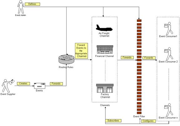
Figure 3 depicts the basic
concepts of how the participating entities collaborate together in the Event
Handler Functional Element. Beginning with the event supplier who generates an
event, the event is subsequently routed to the routing rules engine. Depending
on the rules specified by the event administrator on the engine, the event
could be routed to an appropriate channel, for example, the airfreight channel.
In this case, a notification message will be sent to the subscribing event
consumers. In between that, there is a filtering engine to determine if a
particular event is meaningful to the intended recipients and this is
configurable by the recipients themselves.
2.3.3 Key Features
Implementations of the Event Handler Functional Element are expected to provide the following key features:
1. The Functional Element MUST provide the capability to manage the creation (or registration) and deletion of instances of the following concepts based on a pre-defined structure:
1.1. Event Supplier,
1.2. Event Consumer,
1.3. Event,
1.4. Filter,
1.5. Channel, and
1.6. Routing Rule.
2. The Functional Element MUST provide the capability to manage all the information (attribute values) stored in such concepts. This includes the capability to retrieve and update attribute’s values belonging to the concepts mentioned in Key Feature (1).
3. The Functional Element MUST provide the capability to enable Event Suppliers to trigger relevant Events.
4. The Functional Element MUST provide a mechanism to associate/unassociate Routing Rules to an Event.
Example: As shown in Figure 1, where an event can be
routed to Air Freight or Financial Channel or even to all channels based on the
Routing Rules that are associated with the Event.
5. As part of Key Feature (3), the Routing Rules must be able to route an event to all, specified Channels or individual Event Consumers.
6. The Functional Element MUST enable Event Consumers to execute the following tasks to improve the relevancy of the incoming events”
6.1. Subscribe/Unsubscribe to relevant Channel(s), and
6.2. Apply a filter to the appropriate channel or event, which helps to refine the criteria of a useful event further.
7. The Functional Element MUST provide the capability to notify relevant Event Consumers when an event occurs.
Examples of notification types include SMS, email and Web Services invocations.
8.
As part of Key Feature (6), the notification
must be able to handle differing requirements arising from different notification
formats.
Example: If the incoming event contains 2 important
attributes, the order or position of these 2 attributes must be configurable to
suit the convenience of the Event Consumer. This is extremely important in the
case of Web Service Invocations.
10. The Functional Element MUST provide a mechanism for managing the concepts specified across different application domains.
Example: Namespace
control mechanism
In addition, the following key features could be provided to enhance the Functional Element further:
1.
The Functional Element MAY provide a mechanism
to enable active event detection.
2.
If Key Feature (1) is implemented, then the
Functional Element MUST provide the following capabilities also:
2.1. Non-intrusive
detection
Example:
The detection of a new event through periodic inspection of the audit log.
2.2. Configurable
event detection schedule
Example:
To inspect the audit log every 2 hours, where the duration between inspections
is configurable.
2.3. Ability
to retrieve relevant data from external source(s) for further event processing
by Event Handler
Example:
To retrieve Error Type and Message from audit log.
3. The Functional Element MAY provide the capability to record event processing within the Event Handler. The logging of event processing includes the occurrences of event, sending of notifications, warning and error messages generated in the processing of events.
4. The Functional Element MAY provide the capability scheduled-based event notification.
2.3.4 Interdependencies
|
Direct
Dependency |
|
|
Log Utility Functional Element |
The Log Utility Functional Element helps to log the audit trial. |
|
|
|
|
Notification Functional Element |
The Notification Functional Element helps to send SMS and email to the appropriate Event Consumer. |
2.3.5 Related Technologies and Standards
None
2.3.6 Model
|
|
|
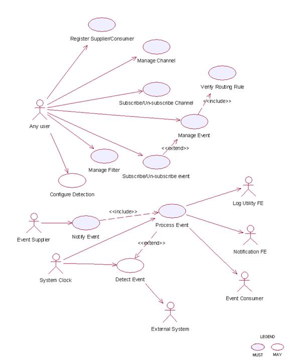
Figure 7: Model Of the Event Handler Functional Element [[4]] |
2.3.7 Usage Scenarios
2.3.7.1 Register Supplier/Consumer
2.3.7.1.1 Description
This
use case allows the user to register itself to the Event Handler Functional
Element as an event supplier or an event consumer.
2.3.7.1.2 Flow of Events
2.3.7.1.2.1 Basic Flow
The use case begins when the user of the Event Handler wants to register an event supplier or event consumer with the Event Handler.
1: The user sends a request to Event Handler together with its profile data and operation.
2: Based on the operation it specified, one of the following sub-flows is executed:
If the operation is ‘Register as supplier’, then sub-flow 2.1 is executed.
If the operation is ‘Register as consumer’, then sub-flow 2.2 is executed.
If the operation is ‘Un-register as supplier’, then sub-flow 2.3 is executed.
If the operation is ‘Un-register as consumer’, then sub-flow 2.4 is executed.
If the operation is ‘Update supplier’, then sub-flow 2.5 is executed.
If the operation is ‘Update consumer’, then sub-flow 2.6 is executed.
If the operation is ‘Retrieve supplier’, then sub-flow 2.7 is executed.
If the operation is ‘Retrieve consumer’, then sub-flow 2.8 is executed.
2.1: Register as Supplier.
2.1.1: The Functional Element gets the user profile data, i.e. namespace, name, description and type.
2.1.2: The Functional Element registers the user as event supplier.
2.1.3: The Functional Element returns the Supplier Id to the user.
2.2: Register as Consumer.
2.2.1: The Functional Element gets the user profile data, i.e. namespace, name, description and type.
2.2.2: The Functional Element registers the user as event consumer.
2.2.3: The Functional Element returns the Consumer Id to the user.
2.3: Un-register as Supplier.
2.3.1: The Functional Element gets the user namespace and name or User Id.
2.3.2: The Functional Element checks whether the user is a supplier.
2.3.3: The Functional Element removes the user as supplier.
2.4: Un-register as Consumer.
2.4.1: The Functional Element gets the user namespace and name or User Id.
2.4.2: The Functional Element checks whether the user is a consumer.
2.4.3: The Functional Element removes the user as consumer.
2.5: Update Supplier.
2.5.1: The Functional Element gets the user namespace and name or User Id together with the user profile.
2.5.2: The Functional Element checks whether the user is a supplier.
2.5.2: The Functional Element updates the user profile.
2.6: Update Consumer.
2.6.1: The Functional Element gets the user namespace and name or User Id together with the user profile.
2.6.2: The Functional Element checks whether the user is a consumer.
2.6.3: The Functional Element updates the user profile.
2.7: Retrieve Supplier.
2.7.1: The Functional Element gets the user namespace and name or User Id.
2.7.2: The Functional Element checks whether the user is a supplier.
2.7.3: The Functional Element returns the user profile.
2.8: Retrieve Consumer.
2.8.1: The Functional Element gets the user namespace and name or User Id.
2.8.2: The Functional Element checks whether the user is a consumer.
2.8.3: The Functional Element returns the user profile.
2.3.7.1.2.2 Alternative Flows
1: Supplier Already Registered.
1.1: If in the basic flow 2.1.2, the user already registered as supplier, Functional Element will return an error message to the user and the use case ends.
2: Consumer Already Registered.
2.1: If in the basic flow 2.2.2, the user already registered as consumer, Functional Element will return an error message to the user and the use case ends.
3: Supplier or Consumer Not Registered.
3.1: If in the basic flow 2.3.2, 2.4.2, 2.5.2, 2.6.2, 2.7.2, and 2.8.2, the user specified is not registered, Functional Element will return an error message to the user and the use case ends.
4: Persistency Mechanism Error.
4.1: If in the basic flow 2.1, 2.2, 2.3, 2.4, 2.5, 2.6, 2,7 and 2.8, the Functional Element cannot perform data persistency, Functional Element will return an error message to the user and the use case ends.
2.3.7.1.3 Special Requirements
None.
2.3.7.1.4 Pre-Conditions
None.
2.3.7.1.5 Post-Conditions
None.
2.3.7.2 Manage Channel
2.3.7.2.1 Description
This use case allows the user to manage channels.
2.3.7.2.2 Flow of Events
2.3.7.2.2.1 Basic Flow
The use case begins when the user wants to create/retrieve/update/delete a channel
1: The user sends request to manipulate a channel.
2: Based on the operation it specifies, one of the following sub-flows is executed:
If the operation is ‘Create Channel’, the sub-flow 2.1 is executed.
If the operation is ‘Retrieve Channel’, the sub-flow 2.2 is executed.
If the operation is ‘Update Channel’, the sub-flow 2.3 is executed.
If the operation is ‘Delete Channel’, the sub-flow 2.4 is executed.
2.1: Create Channel.
2.1.1: The Functional Element gets channel definition, i.e. namespace, channel name and description.
2.1.2: The Functional Element checks whether the channel exists.
2.1.3: The Functional Element creates the channel.
2.2: Retrieve Channel.
2.2.1: The Functional Element gets namespace, channel name and retrieve condition.
2.2.2: The Functional Element retrieves the channel’s information according to the condition.
2.3: Update Channel.
2.3.1: The Functional Element gets namespace, channel name and description.
2.3.2: The Functional Element checks whether the channel exists.
2.3.3: The Functional Element updates the channel definition.
2.4: Delete Channel.
2.4.1: The Functional Element gets namespace and channel name.
2.4.2: The Functional Element checks whether the channel exists.
2.4.3: The Functional Element removes the channel from the Functional Element.
3: The Functional Element returns the results of the operation to the user and the use case ends.
2.3.7.2.2.2 Alternative Flows
1: Channel Already Exists.
1.1: If in the basic flow 2.1.2, the channel is already defined, Functional Element returns an error message and the use case ends.
2: Conditional Retrieving.
2.1: In the basic flow 2.2.2:
2.1 1: If the condition is the retrieval by channel name and the channel does not exist, then it will go to Alternative Flow 3.
2.1.2: If the condition is the retrieval of one channel definition, it returns the definition of that channel and the use case ends.
2.1.3: If the condition is the retrieval of all channels’ information, it returns all channels definition and the use case ends.
2.1.4: If the condition is the retrieval of channel through channel description, it will return all matched channels and the use case ends.
2.1.5: If the condition is the retrieval of registered consumers, it returns the list of consumer registered on the channel and the use case ends.
3: Channel Not Found.
3.1: If in the basic flow 2.2.2, 2.3.2 and 2.4.2, the channel does not exist, Functional Element will return an error message and the use case ends.
4: Consumer Not Found.
4.1: If in the basic flow 2.1.3, 2.5.3 and 2.6.3, the event consumer does not exist, Functional Element will return an error message and the use case ends.
5: Extension Point.
5.1: If in the basic flow 2.1.3, and 2.3.3, the event consumers that subscribed to the channel are provided, the use case Subscribe/un-subscribe channel will be extended.
2.3.7.2.3 Special Requirements
None.
2.3.7.2.4 Pre-Conditions
None.
2.3.7.2.5 Post-Conditions
None.
2.3.7.3 Subscribe/Un-subscribe To Channel
2.3.7.3.1 Description
This use case performs the subscription or un-subscription on a channel for an event consumer.
2.3.7.3.2 Flow of Events
2.3.7.3.2.1 Basic Flow
The use case begins when the user wants to subscribe or un-subscribe to a channel.
1: The user sends the request.
2: Based on the operation it specifies, one of the following sub-flows is executed:
If the operation is ‘Subscribe to Channel’, then sub-flow 2.1 is executed.
If the operation is ‘Un-Subscribe to Channel’, then sub-flow 2.2 is executed.
2.1: Subscribe To Channel.
2.1.1: The Functional Element gets event consumer Id, or consumer namespace and consumer name, together with channel namespace and channel name.
2.1.2: The Functional Element checks whether the channel exists.
2.1.3: The Functional Element adds the subscription of the consumer to the channel.
2.2: Un-Subscribe To Channel.
2.2.1: The Functional Element gets event consumer Id, or consumer namespace and consumer name, together with channel namespace and channel name.
2.2.2: The Functional Element checks whether the channel exists.
2.2.3: The Functional Element removes the subscription of the consumer to the channel.
3: The Functional Element returns the results of the operation to the user and the use case ends.
2.3.7.3.2.2 Alternative Flows
1: Channel Not Found.
1.1: If in the basic flow 2.1.2 and 2.2.2, the channel specified does not exist, Functional Element will return an error message to the user and the use case ends.
2: Event Consumer Not Found.
2.1: If in the basic flow 2.1.2 and 2.2.2, the event consumer related does not exist, Functional Element will return an error message to the user and the use case ends.
2.3.7.3.3 Special Requirements
None.
2.3.7.3.4 Pre-Conditions
None.
2.3.7.3.5 Post-Conditions
None.
2.3.7.4 Manage Event
2.3.7.4.1 Description
This use case describes the scenarios of managing events.
2.3.7.4.2 Flow of Events
2.3.7.4.2.1 Basic Flow
The use case begins when the user wants to manage events.
1: The user sends a request to the Functional Element.
2: Based on the operation it specifies, one of the following sub-flows is executed:
If the operation is ‘Create Event’, then sub-flow 2.1 is executed.
If the operation is ‘Retrieve Event Information’, then sub-flow 2.2 is executed.
If the operation is ‘Update Event Definition’, then sub-flow 2.3 is executed.
If the operation is ‘Delete Event’, then sub-flow 2.4 is executed.
If the operation is ‘Assign Flow’, then sub-flow 2.5 is executed.
If the operation is ‘Un-Assign Flow’, then sub-flow 2.6 is executed.
2.1: Create Event
2.1.1: The Functional Element gets event definition including namespace, event name, event description, event routing rule, and event attributes definition.
2.1.2: The Functional Element verifies the parameters.
2.1.3: The Functional Element verifies the routing rule through use case verify routing rule.
2.1.4: The Functional Element creates event definition by recording the definition of event.
2.2: Retrieve Event.
2.2.1: The Functional Element gets namespace, event name, and condition.
2.2.2: The Functional Element retrieves the event definition according to the condition.
2.3: Update Event Definition
2.3.1: The Functional Element gets event definition including namespace, event name, event description, event routing rule, and event attributes definition.
2.3.2: The Functional Element verifies the parameters.
2.3.3: The Functional Element verifies the routing rule through use case verify routing rule.
2.3.4: The Functional Element updates the event definition.
2.4: Delete Event.
2.4.1: The Functional Element gets namespace and event name.
2.4.2: The Functional Element checks whether the event exists.
2.4.3: The Functional Element deletes the event definition.
2.5: Assign Flow.
2.5.1: The Functional Element gets namespace, event name and flow name.
2.5.2: The Functional Element checks whether the event exists and flow defined.
2.5.3: The Functional Element assigns the flow to the event.
2.6: Un-assign Flow.
2.6.1: The Functional Element gets namespace, event name and flow name.
2.6.2: The Functional Element checks whether the event exists and flow defined.
2.6.3: The Functional Element un-assigns the flow to the event.
3: The Functional Element returns the results of the operation to the user and the use case ends.
2.3.7.4.2.2 Alternative Flows
1: Event Already Exist.
1.1: If in the basic flow 2.1.2, the event already exists, Functional Element will return an error message to the user and the use case ends.
2: Parameters Are Invalid.
2.1: If in the basic flow 2.1.2 and 2.3.2, the parameters provided are invalid, Functional Element will return an error message to the user and the use case ends.
3: Event Not Found.
3.1: If in the basic flow 2.2.2, 2.3.2 and 2.4.2, the event does not exist, Functional Element will return an error message to the user and the use case ends.
4: Flow Not Defined.
4.1: If in the basic flow 2.1.2 and 2.3.2, the flow does not exist, Functional Element will return an error message to the user and the use case ends.
5: Condition Retrieve.
5.1: In the basic flow 2.2.2:
5.1.1: If the retrieving condition is the retrieval of event definition based on event name, it returns event definition and the use case ends.
5.1.2: If the retrieving condition is the retrieval of all event definition, it returns all event definition and the use case ends.
5.1.3: If the retrieving condition is the retrieval of events assigned to specified channel, it returns the list of event definitions.
5.1.4: If the retrieving condition is the retrieval of channels associated with specified event, it returns the list of channel definition.
6: Extension Point.
6.1: If in the basic flow 2.1.4, and 2.3.4, the event consumers that subscribed to the event are provided, the use case Subscribe/Un-subscribe event will be extended.
2.3.7.4.3 Special Requirements
None.
2.3.7.4.4 Pre-Conditions
None.
2.3.7.4.5 Post-Conditions
None.
2.3.7.5 Subscribe/Un-subscribe To Event
2.3.7.5.1 Description
This use case performs the subscription or un-subscription on an event for an event consumer.
2.3.7.5.2 Flow of Events
2.3.7.5.2.1 Basic Flow
The use case begins when the user wants to subscribe or un-subscribe an event.
1: The user sends a request.
2: Based on the operation it specifies, one of the following sub-flows is executed:
If the operation is ‘Subscribe to Event’, then sub-flow 2.1 is executed.
If the operation is ‘Un-Subscribe to Event’, then sub-flow 2.2 is executed.
2.1: Subscribe To Event.
2.1.1: The Functional Element gets event consumer Id, or consumer namespace and consumer name, together with event namespace and event name.
2.1.2: The Functional Element checks whether the event exists.
2.1.3: The Functional Element adds the subscription of the consumer to the event.
2.2: Un-Subscribe To Event.
2.2.1: The Functional Element gets event consumer Id, or consumer namespace and consumer name, together with event namespace and event name.
2.2.2: The Functional Element checks whether the event exists.
2.2.3: The Functional Element removes the subscription of the consumer to the event.
3: The Functional Element returns the results of the operation to the user and the use case ends.
2.3.7.5.2.2 Alternative Flows
1: Event Not Found.
1.1: If in the basic flow 2.1.2 and 2.2.2, the event specified does not exist, Functional Element will return an error message to the user and the use case ends.
2: Event Consumer Not Found.
2.1: If in the basic flow 2.1.2 and 2.2.2, the event consumer related does not exist, Functional Element will return an error message to the user and the use case ends.
2.3.7.5.3 Special Requirements
None.
2.3.7.5.4 Pre-Conditions
None.
2.3.7.5.5 Post-Conditions
None.
2.3.7.6 Verify Routing Rule
2.3.7.6.1 Description
This use case verifies the syntax of routing rule.
2.3.7.6.2 Flow of Events
2.3.7.6.2.1 Basic Flow
The use case begins when the user wants to verify the correctness of a routing expression.
1: The user sends a request.
2: The Functional Element gets the routing expression.
3: The Functional Element checks the syntax of routing expression.
4: The Functional Element verifies the parameters.
5: The Functional Element returns the status of the operation to the user and the use case ends.
2.3.7.6.2.2 Alternative Flows
1: Routing Rule Expression Syntax Error.
1.1: If in the basic flow 3, there is a syntax error, Functional Element will return an error message to the user and the use case ends.
2: Event Consumer Not Found.
2.1: If in the basic flow 4, the event consumer related does not exist, Functional Element will return an error message to the user and the use case ends.
2.3.7.6.3 Special Requirements
None.
2.3.7.6.4 Pre-Conditions
None.
2.3.7.6.5 Post-Conditions
None.
2.3.7.7 Manage Filter
2.3.7.7.1 Description
A filter is used to filter out certain events to those event consumers even though they are the intended receivers according to the routing rules.
2.3.7.7.2 Flow of Events
2.3.7.7.2.1 Basic Flow
The use case begins when the user wants to create/retrieve/update/delete a filter.
1: The user sends a request to manage a filter.
2: Based on the operation it specifies, one of the following sub-flows is executed:
If the operation is ‘Create Filter’, then sub-flow 2.1 is executed.
If the operation is ‘Retrieve Filter’, then sub-flow 2.2 s executed.
If the operation is ‘Update Filter’, then sub-flow 2.3 is executed.
If the operation is ‘Delete Filter’, then sub-flow 2.4 is executed.
2.1: Create Filter.
2.1.1: The Functional Element gets filter definition, i.e. consumer namespace, consumer name, filter name, description, event name or channel name.
2.1.2: The Functional Element checks whether the event or channel exists.
2.1.3: The Functional Element saves the filter definition.
2.2: Retrieve Filter.
2.2.1: The Functional Element gets the filter name.
2.2.2: The Functional Element retrieves the filter information according to the name.
2.3: Update Filter.
2.3.1: The Functional Element gets filter definition, i.e. consumer namespace, name, filter name, description, event name or channel name.
2.3.2: The Functional Element checks the parameters.
2.3.3: The Functional Element updates the filter definition.
2.4: Delete Filter.
2.4.1: The Functional Element gets namespace and filter name.
2.4.2: The Functional Element checks whether the filter exists.
2.4.3: The Functional Element removes the filter from the Functional Element.
3: The Functional Element returns the results of the operation to the user and the use case ends.
2.3.7.7.2.2 Alternative Flows
1: Filter Already Exists.
1.1: If in the basic flow 2.1.2, the filter is already defined, Functional Element will return an error message and the use case ends.
2: Event Not Found.
2.1: If in the basic flow 2.1.2 and 2.3.2, the event used does not exist, Functional Element will return an error message and the use case ends.
3: Channel Not Found.
3.1: If in the basic flow 2.1.2 and 2.3.2, the channel used does not exist, Functional Element will return an error message and the use case ends.
4: Consumer Not Found.
4.1: If in the basic flow 2.1.3, 2.5.3, and 2.6.3, the event consumer does not exist, Functional Element will return an error message and the use case ends.
2.3.7.7.3 Special Requirements
None.
2.3.7.7.4 Pre-Conditions
None.
2.3.7.7.5 Post-Conditions
None.
2.3.7.8 Notify Event
2.3.7.8.1 Description
This use case allows the event supplier to notify an event to the Event Handler Functional Element. Once the Event Handler Functional Element receives the notification, it will process the event based on the processing logic defined.
2.3.7.8.2 Flow of Events
2.3.7.8.2.1 Basic Flow
The use case begins when the user wants to notify an event.
1: The user sends a notification.
2: The Functional Element receives the notification with parameters, i.e. event supplier id or event supplier namespace and name.
3: The Functional Element checks whether the event is defined and event supplier is registered.
4: Include use case Process Event to process the notification of event.
5: The Functional Element returns the status of the operation to the user and the use case ends.
2.3.7.8.2.2 Alternative Flows
1: User Is Not Registered.
1.1: If in the basic flow 3, the user is not registered, Functional Element will return an error message to the user and the use case ends.
2: Event Not Defined.
2.1: If in the basic flow 3, the event is not defined, Functional Element will return an error message to the user and the use case ends.
3: Error Returned.
3.1: If in the basic flow 4, an error is returned by use case Process event, Functional Element will return an error message to the user and the use case ends.
2.3.7.8.3 Special Requirements
None.
2.3.7.8.4 Pre-Conditions
None.
2.3.7.8.5 Post-Conditions
None.
2.3.7.9 Configure Monitoring
2.3.7.9.1 Description
This use case describes the capability of configuration on event monitoring. Based on the configuration, Event Handler will pro-actively check whether an event has happened.
2.3.7.9.2 Flow of Events
2.3.7.9.2.1 Basic Flow
The use case begins when the user wants to configure the event monitoring.
1: The user sends a request to manage a filter.
2: Based on the operation it specifies, one of the following sub-flows is executed:
If the operation is ‘Add Configuration’, then sub-flow 2.1 is executed.
If the operation is ‘Remove Configuration’, then sub-flow 2.2 is executed.
2.1: Add Configuration.
2.1.1: The Functional Element gets configuration definition, i.e. configuration name, namespace, event name, connection parameters, condition that signifies the events and schedule.
2.1.2: The Functional Element saves filter definition.
2.2: Remove Configuration.
2.2.1: The Functional Element gets configuration name.
2.2.2: The Functional Element removes the configuration.
3: The Functional Element returns the results of the operation to the user and the use case ends.
2.3.7.9.2.2 Alternative Flows
1: Configuration Exist.
1.1: If in the basic flow 2.1.2, the configuration already exists, Functional Element will return an error message and the use case ends.
2.3.7.9.3 Special Requirements
None.
2.3.7.9.4 Pre-Conditions
None.
2.3.7.9.5 Post-Conditions
None.
2.3.7.10 Detect Event
2.3.7.10.1 Description
This use case describes the event monitoring capability that Event Handler provides. Once Event Handler detects an event, it will trigger the pre-defined process for the event.
2.3.7.10.2 Flow of Events
2.3.7.10.2.1 Basic Flow
The use case begins when the Functional Element clock generates the trigger.
1: The Functional Element clock generates a trigger.
2: The Functional Element receives the trigger and checks the condition for pre-defined monitoring sources.
3: The Functional Element checks whether the event happens.
4: The Functional Element returns the results of the operation and the use case ends.
2.3.7.10.2.2 Alternative Flows
1: External Functional Element Not Available.
1.1: If in the basic flow 3, the external Functional Element is not available and the Event Handler cannot make a connection, Functional Element will return an error message and the use case ends.
2: Data Not Available.
2.1: If in the basic flow 3, the data that signifies the event cannot be accessed, Functional Element will return an error message and the use case ends.
3: Extension Point.
3.1: If in the basic flow 3, the event happens, Functional Element will extend to use case Process event.
2.3.7.10.3 Special Requirements
None.
2.3.7.10.4 Pre-Conditions
None.
2.3.7.10.5 Post-Conditions
None.
2.3.7.11 Process Event
2.3.7.11.1 Description
2.3.7.11.2 Flow of Events
2.3.7.11.2.1 Basic Flow
The use case begins when there is a request to process the event.
1: The user sends a request to process an event.
2: Based on the actor of this use case, one of the sub-flows is executed.
If the initiator is the Functional Element clock, then sub-flow ‘Initiated By Functional Element Clock’ is executed.
If the initiator is other than Functional Element clock, then sub-flow ‘Initiated By Any User’ is executed.
2.1: Initiated By Functional Element Clock.
2.1.1: The Functional Element looks up scheduled events defined to find out time-due notification.
2.1.2: The Functional Element retrieves the routing rule for the event.
2.1.3: The Functional Element looks up the corresponding consumers based on the routing rule.
2.1.4: The Functional Element retrieves filters defined and find out the event receivers.
2.1.5: The Functional Element notifies or invokes the event consumers based on the routing rule defined.
2.2: Initiated By Any User.
2.2.1: The Functional Element retrieves the routing rule for the event.
2.2.2: The Functional Element looks up the corresponding consumers.
2.2.3: The Functional Element retrieves filters defined and find out the event receivers.
2.2.4: The Functional Element notifies or invokes the event consumers based on the routing rule defined.
3: The Functional Element logs the notification of event and the use case ends.
2.3.7.11.2.2 Alternative Flows
1: Notify Event.
In basic flow 2.1.4 and 2.2.4, based on the type of consumer, one of the sub-flows is execute.
If the consumer type is ‘SMTP’, then sub-flow Notify via SMTP is executed.
If the consumer type is ‘SMS Gateway’, then sub-flow Notify via SMS Gateway is executed.
If the consumer type is ‘Notify RPC-Web Service’, then sub-flow Notify RPC-Web Service is executed.
If the consumer type is ‘Notify Document Style Web Service’ then sub-flow Notify Document style Web Service is executed.
1.1: Notify via SMTP.
1.1.1: The Functional Element gets the pre-defined message for event and forms the parameters.
1.1.2: The Functional Element gets the parameters for SMTP server.
1.1.3: The Functional Element sends out the pre-defined message and the use case ends.
1.2: Notify via SMS Gateway.
1.2.1: The Functional Element gets the pre-defined message for event and forms the parameters.
1.2.2: The Functional Element gets the parameters for the SMS gateway.
1.2.3: The Functional Element sends out the pre-defined message and the use case ends.
1.3: Notify RPC-Web Service.
1.3.1: The Functional Element gets the operation parameter.
1.3.2: The Functional Element gets Web Services endpoint parameters.
1.3.3: The Functional Element dynamically invokes the Web Service and the use case ends.
1.4: Notify Document Style Web Service.
1.4.1: The Functional Element gets the operation parameter.
1.4.2: The Functional Element gets Web Services endpoint parameters.
1.4.3: The Functional Element dynamically generates the SOAP message and sends to the Web Services and the use case ends.
2: Flow Is Defined.
If in the basic flow 2.1.2 and 2.2.1, a flow is defined for the event, Functional Element will perform the following steps:
2.1: The Functional Element retrieves all the intended event consumers defined in the flow.
2.2: The Functional Element will go to basic flow 2.2.
2.3: The Functional Element will resume the execution from basic flow 2.1.2 or 2.2.1.
3: Log Utility Not Available.
3.1: If in the basic flow 3, the Log Utility Functional Element is not available, Functional Element will return an error message to the user and the use case ends.
4: SMS Gateway Not Available.
4.1: If in the Alternative Flow 1.2.3, the SMS Gateway is not available, Functional Element will return an error message to the user and the use case ends.
5: SMPT Server Not Available.
5.1: If in the Alternative Flow 1.1.3, the SMTP server is not available, Functional Element will return an error message to the user and the use case ends.
6: RPC Web Service Not Available.
6.1: If in the Alternative Flow 1.3.3, the Web Service is not available, Functional Element will return an error message to the user and the use case ends.
7: Document Style Web Service Not Available.
7.1: If in the Alternative Flow 1.4.3, document style Web Service is not available, Functional Element will return an error message to the user and the use case ends.
2.3.7.11.3 Special Requirements
2.3.7.11.3.1 Supportability
The application server used must have a JMS service provided.
2.3.7.11.4 Pre-Conditions
None.
2.3.7.11.5 Post-Conditions
None.
2.4 Group Management Functional Element
2.4.1 Motivation
The Group Management Functional Element is expected to be an integral part of the User Access Management (UAM) functionalities. In a Web Service-enabled implementation, this Functional Element helps to provide the mechanism to manage users in a collective manner. This is important as it provides the flexibility of adopting either coarse or fine-grain access controls, or both.
Primary Requirements
·
MANAGEMENT-050 to MANAGEMENT-053, and
·
MANAGEMENT-078
Secondary Requirements
·
None
2.4.2 Terms Used
|
Terms |
Description |
|
Group |
A Group is a collection of individual users, and are typically grouped together as they have certain commonalities |
|
Namespace |
Namespace is use to segregate the instantiation of the application across different application domains. If a company has two separate standalone application, for example, an email application and an equipment booking application, then these two are considered as separate application domains. |
|
User |
A user is loosely defined to include both human and virtual users. Virtual users could include service users and application (or machine) users that are utilising other services in a SOA environment. |
|
User Access Management / UAM |
User Access Management or UAM refer to the concept of managing users in a holistic manner, considering all aspect which includes: Defining a set of basic user information that should be stored in any enterprise application. Providing a means to extend this basic set of user information when needed. Simplifying management by grouping related users together through certain criteria. Having the flexibility of adopting both coarse and fine grain access controls. |
2.4.3 Key Features
Implementations of the Group Management Functional Element are expected to provide the following key features:
1. The Functional Element MUST provide a basic Group structure with a set of pre-defined attributes.
2. The Functional Element MUST provide the capability to extend on the basic Group structure dynamically.
3. As part of Key Feature (2), this dynamic extension MUST be definable and configurable at runtime implementation of the Functional Element.
4. The Functional Element MUST provide the capability to manage the creation and deletion of instances of Groups based on defined structure.
5. The Functional Element MUST provide the capability to manage all the information (attribute values) stored in such Groups. This includes the capability to retrieve and update attribute’s values belonging to a Group.
6. The Functional Element MUST provide a mechanism to manage the collection of users in a Group. This includes the capability to create, retrieve, update and delete users belonging to a Group.
7. The Functional Element MUST provide a mechanism for managing Groups across different application domains.
Example:
Namespace control mechanism
In addition, the following key features could be provided to enhance the Functional Element further:
1. The Functional Element MAY provide a mechanism to enable different Groups to be related to one another.
2. The Functional Element MAY also provide a mechanism to enable hierarchical relationships between Groups.
Example:
Parent and Child Relationship.
3. As an extension of Key Feature (2), the Functional Element MAY also provide the capability to enable Groups to be part of the collection of “users” of another Group.
Example:
Adding of Group “Dept-A” to “Company-XYZ”
– “Dept-A” is a Group, and also part of the collection of Group “Company-XYZ”.
4. The Functional Element MAY provide validity checks when managing information stored in a Group.
Example:
Adding of User “john” – A validity check
could be imposed to ensure that a user “john” exists before adding to into the
Group.
2.4.4 Interdependency
|
Direct Dependency |
|
|
User Management Functional Element |
The User Management Functional Element is used to manage the user’s attributes. The Group Management Functional Element in turn provides useful aggregation of the users. Together, they are able to achieve effective and efficient management of user information. |
2.4.5 Related Technologies and Standards
None.
2.4.6 Model
|
|
|
Figure 8: Model Of the Group Management Functional Element [[5]] |

2.4.7 Usage Scenarios
2.4.7.1 Manage Group
This use case describes the management of a group, namely the creation, deletion, retrieval and update of the group.
2.4.7.1.1 Flow of Events
2.4.7.1.1.1 Basic Flow
This use case starts when the user wants to manage group.
If user wants to ‘Create Group’, then basic flow 1 is executed.
If user wants to ‘Retrieve Group’, then basic flow 2 is executed.
If user wants to ‘Update Group’, then basic flow 3 is executed.
If user wants to ‘Delete Group’, then basic flow 4 is executed.
1: Create Group.
1.1: User provides the basic information that is necessary for creating a group.
1.2: Functional Element creates the group and the use case ends.
2: Retrieve Group.
2.1: User provides the necessary information for retrieving the complete group’s attributes.
2.2: Functional Element returns the group’s information and the use case ends.
3: Update Group.
3.1: User provides the necessary information for updating the group’s attributes.
3.2: Functional Element updates the group and the use case ends.
4: Delete Group.
4.1: User provides the necessary information for deleting a particular group.
4.2: Functional Element deletes the group and the use case ends.
2.4.7.1.1.2 Alternative Flows
1: Group Exist.
1.1: In basic flow 1.2, Functional Element detects an identical group. Functional Element returns an error message and the use case ends.
2: Group Does Not Exist.
2.1: In basic flow 2.2, 3.2 and 4.2, Functional Element cannot find a group that matches the user’s criteria. Functional Element returns an error message and the use case ends.
3: Save Updated Information.
3.1: In basic flow 1.2, 2.2, 3.2 and 4.2, Functional Element fails to save the updated information. Functional Element returns an error message and the use case ends.
2.4.7.1.2 Special Requirements
None.
2.4.7.1.3 Pre-Conditions
None.
2.4.7.1.4 Post-Conditions
None.
2.4.7.2 Manage Group Members
2.4.7.2.1 Description
This use case is an extension of the manage group use case. Specifically, it describes the scenarios to manage members in the group.
2.4.7.2.2 Flow of Events
2.4.7.2.2.1 Basic Flow
This use case starts when the user wants to manage members in a group.
If user wants to ‘Create Members In A Group’, then basic flow 1 is executed.
If user wants to ‘Retrieve Members From A Group’, then basic flow 2 is executed.
If user wants to ‘Delete Members From A
Group’, then basic flow 3 is executed.
1: Create Members In A Group.
1.1: User provides the necessary information for retrieving the group.
1.2: Functional Element adds members to the group and the use case ends.
2: Retrieve Members In A Group.
2.1: User provides the necessary information for retrieving the group.
2.2: Functional Element returns the members and the use case ends.
3: Delete Members From Group.
3.1: User provides the necessary information for retrieving the group.
3.2: User provides the necessary information for deleting members in the group.
3.3: Functional Element deletes members from group and the use case ends.
2.4.7.2.2.2 Alternative Flows
1: Group Does Not Exist.
1.1: In basic flow 1.1, 2.1 and 3.1, Functional Element cannot find the group requested. Functional Element returns an error message and the use case ends.
2: Members Does Not Exist
2.1: In basic flow 3.3, the Functional Element attempts to delete a non-existence member. Functional Element returns an error message and the use case ends.
2.4.7.2.3 Special Requirements
None.
2.4.7.2.4 Pre-Conditions
None.
2.4.7.2.5 Post-Conditions
None.
2.4.7.3 Manage Group Dynamic Definition
2.4.7.3.1 Description
This use case describes scenario involved in managing the dynamic group definition.
2.4.7.3.2 Flow of Events
2.4.7.3.2.1 Basic Flow
This use case starts when the user wants to manage dynamic group definition. This include create, retrieve, update and delete dynamic group definition.
If user wants to ‘Create Dynamic Definition For A Group’, then basic flow 1 is executed.
If user wants to ‘Retrieve Dynamic Definition For A Group’, then basic flow 2 is executed.
If user wants to ‘Delete Dynamic Definition For A Group’, then basic flow 3 is executed.
If user wants to ‘Update Dynamic Definition For A Group’, then basic flow 4 is executed.
1: Create Dynamic Definition For A Group.
1.1: User provides the additional definition for the group.
1.2: Functional Element creates the additional definition for the group and the use case ends.
2: Retrieve Dynamic Definition For A Group.
2.1: User provides the necessary information to retrieve a particular group.
2.2: Functional Element returns the additional definition for the group and the use case ends.
3: Delete Dynamic Definition For Group.
3.1: User provides the necessary information to retrieve a particular group.
3.2: Functional Element deletes the dynamic definition belonging to the group and the use case ends.
4: Update Dynamic Definition For Group.
4.1: User provides the necessary information to retrieve a particular group.
4.2: User provides the necessary dynamic definition that needs to be updated.
4.3: Functional Element update the dynamic definition and the use case ends.
2.4.7.3.2.2 Alternative Flows
1: Group Does Not Exist.
1.1: In basic flow 1.1, 2.1, 3.1 and 4.1, Functional Element cannot find the group specified. Functional Element returns an error message and the use case ends.
2: Dynamic Group Definition Already Exists.
2.1: In basic flow 1.2, Functional Element returns the error message and the use case ends.
3: Dynamic Group Definition Does Not Exist.
3.1: In basic flow 4.3, Functional Element cannot update the dynamic group definition. Functional Element returns an error message and the use case ends.
2.4.7.3.3 Special Requirements
None.
2.4.7.3.4 Pre-Conditions
None.
2.4.7.3.5 Post-Conditions
None.
2.5
Identity
Management Functional Element
2.5.1
Motivation
As secured Web Services become rampant, with each having its own
authentication and authorisation management, users are finding it difficult to
keep track of their accounts and passwords. Through the use of Identity
Management, users can now voluntarily establish links between their accounts so
that they need not sign in multiple times to access enterprise-level Web
Services. This mechanism is known as Single Sign-On (SSO). SSO can further be
extended to access Web Services from across different business organisations
that have prior agreements to trust and transact with each other (also known as
a circle of trust). This mechanism, which involves federating and signing-in of
identity’s accounts across different trusted organisations, is known as
Federated Identity Single Sign-On.
Identity Management is about the management of information pertaining to
an entity as well as the process of identification, authentication and
authorization of resources to that entity.
Identity management generally covers the following aspects:
Basic user accounts management facilities
User authentication mechanism(s)
User authorisation mechanism(s)
Generation of audit trails for user activities
Primary Requirements
·
SECURITY-001,
·
SECURITY-003
(all),
·
SECURITY
-004 (all),
·
SECURITY
-040 and
·
SECURITY
-041.
Secondary Requirements
·
None
2.5.2
Terms
Used
|
Terms |
Description |
|
Assertion |
Assertion refers to a piece of data produced by an Assertion Authority
regarding either an act of authentication performed on a subject, attribute
information about a subject, or authorization permissions applying to the
subject with respect to a specified resource. |
|
Assertion Authority |
An entity within a trusted circle that provides authentication
assertions. |
|
Access Policy |
A logically defined, executable and testable set of rules or behavior
for access control. |
|
Entity |
Entity can refer to a person, an organization, a resource or a
service. |
|
Federated Identity |
An identity that has been associated, connected or binded with other
accounts for a same given Principal. |
|
Identity |
Identity refers to a set of information that an entity can use to
uniquely describe itself. |
|
Identity Provider |
An entity that creates, maintains, and manages identity information
for Principals and provides Principal authentication to other service
providers within a trusted circle. |
|
Identity Repository |
Identity Repository refers to the storage of the identity information.
Common examples of identity repositories are relational databases, text files
etc. |
|
Principal |
Principal refers to an entity whose identity can be authenticated.
Also known as Subject. |
|
Resource |
A resource in an application is defined to
encompass users, services, data / information, transaction
and security |
|
Security Markup Assertion Language |
Security Markup Assertion Language refers to the set of specifications
describing assertions that are encoded in XML, profiles for attaching the
assertions to various protocols and frameworks, the request/response protocol
used to obtain assertions, and bindings of this protocol to various transfer
protocols (for example, SOAP and HTTP). |
|
Single Sign-On (SSO) |
The ability to use proof of an existing authentication session with an
identity provider to create authenticated sessions with other service
providers. |
|
Subject |
Subject – see Principal. |
Assertion [section 2.3.2]
AudienceRestrictionCondition
[section 2.3.2.1.3]
AuthenticationQuery [section 3.3.3]
AuthenticationStatement [section
2.4.3]
KeyInfo [section 5.4.5]
Request [section 3.2.2]
Response [section 3.4.2]
Subject [section 2.4.2.1]
2.5.3
Key
Features
Implementations of the Identity Management
Functional Element are expected to provide the following key features:
1. The Functional Element MUST be have
the mechanism to access an Identity Repository.
2. The Functional Element MUST provide
the capability to manage the creation and deletion of instances of Identity in
the said Identity Repository.
3. The Functional Element MUST have the
mechanisms to manage all the information (attribute values) stored in such
Identities. This includes the capability to:
3.1. Retrieve and update attribute’s
values belonging to a Identity,
3.2. Encrypt sensitive user information,
3.3. Authenticate a user, and
3.4. Assign/Unassign Access Policy (or
Policies).
Example: Different levels
of privileges to access protected resources.
4. As part of Key Feature (3.3), the
authentication of an Identity MUST be achieved at least through the use of a
password.
5. As part of Key Feature (3.3), the
Functional Element MUST also provide the capability to use an Assertion
Authority for Single Sign-On (SSO) authentication.
6. As part of Key Feature (5), the SSO
message exchange and protocol MUST use an approved standard. Recommendations
are available in section 2.5.5.
7. As part of Key Feature (3.4), a
mechanism MUST be provided to verify the Identity’s Access Policy on protected
Resources.
8. The Functional Element MUST provide
the capability to create audit trails.
Example: Timestamp of an Identity’s access to Resources.
In addition, the following key features could be provided to enhance the
Functional Element further:
1. The Functional Element MAY provide
an Identity Repository.
2. If Key Feature (1) is provided, the
Functional Element MUST provide the capability to manage the creation and
deletion of instances of Identities based on a pre-defined structure.
3. The Functional Element MAY provide
additional storage in the Identity Repository for an Identity to customise its
preferences.
Example: Identity’s preferred
subscription of notifications/alerts for news.
4. The Functional Element MAY provide a
capability to use an Identity Provider for Federated Identity SSO
authentication.
5. If Key Feature (4) is provided, the
Federated Identity SSO message exchange and protocol MUST use an approved
standard.
2.5.4
Interdependencies
|
Direct Dependencies |
|
|
User Management Functional Element |
The User Management Functional Element is being used for account
management. |
|
Role and Access Management Functional Element |
The Role and Access Management Functional Element is
being used for access control and authorization |
|
Log Utility Functional Element |
The Log Utility Functional Element is being used for logging and creation of
audit trails. |
2.5.5
Related
Technologies and Standards
|
Specifications |
Specific References |
|
Web Services Security v1.0 [[6]] |
Web Services Security: SOAP Message Security 1.0 ( |
|
Security Assertion Markup Language (SAML) v1.1. [[7]] |
Assertions and Protocol for the OASIS Security Assertion Markup
Language (SAML) V1.1 – OASIS Standard, Bindings and Profiles for the OASIS Security Assertion Markup Language
(SAML) V1.1 – OASIS Standard, ·
Assertion Schema ·
Protocol Schema |
|
|
|
|
|
Web Services Federation Language ( |
2.5.6
Model
|
|
|
Figure 9: Model Of the Identity Management
Functional Element [[11]] |
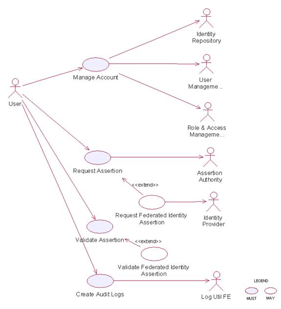
2.5.7
Usage
Scenarios
2.5.7.1
Manage
Account
2.5.7.1.1
Description
This use case
describes the creation/retrieval/update/deletion of an identity’s account. An
identity’s account usually consists of two elements: i) the user information
and ii) the associated access policy.
As Identity
Management Functional Element leverages on the User
Management Functional Elementand Role and Access Management
Functional Element to provide for these functionalities, please refer to
these Functional Elements’ use cases for details.
2.5.7.2
Request
Assertion
2.5.7.2.1 Description
This use case
describes the composition of either 1) an authentication query or 2) an
authorisation decision query and sending it to the assertion authority.
2.5.7.2.2 Flow of Events
2.5.7.2.2.1 Basic Flow
This use case
starts when the user wants to compose a query to the assertion authority.
If the user
requests for an authentication query, then sub-flow 1 is executed.
If the user
requests for an authorisation decision query, then sub-flow 2 is executed.
1: Request for
Authentication Assertion
1.1: The user composes a valid SAML Request with an AuthenticationQuery
and sends it to the assertion authority.
1.2: The user waits for an SAML Response from the assertion authority.
1.3: The user obtains the SAML Assertion from the SAML Response and use
case ends.
2: Request for
Authorisation Decision Assertion
2.1: The user composes a valid SAML Request with an
AuthorizationDecisionQuery and sends it to the assertion authority.
2.2: The user waits for an SAML Response from the assertion authority.
2.3: The user obtains the SAML Assertion from the SAML Response and use
case ends.
2.5.7.2.2.2 Alternative Flows
1: Invalid
Request
1.1: If in basic flow 1.1 or 2.1, if any of the parameters passed into
the request is invalid, the Functional Element flag an exception and use case
ends.
2: Error message
from assertion authority
2.1: If in basic flow 1.3 or 2.3, the assertion authority is unable to
return an assertion (e.g. user has not logged on etc.), it returns an error
code and an error message.
2.2: The Functional Element flag an error with the error message
attached and use case ends.
2.5.7.2.3 Special Requirements
None.
2.5.7.2.4 Pre-Conditions
None.
2.5.7.2.5 Post-Conditions
None.
2.5.7.3
Validate
Assertion
2.5.7.3.1 Description
This use case
describes the validation of either 1) the Authentication Assertion or 2) the
Authorisation Decision Assertion
2.5.7.3.2 Flow of Events
2.5.7.3.2.1 Basic Flow
This use case
starts when the user wants to check if the assertion it is a valid assertion
from the assertion authority.
1: The user
passes the assertion to the Functional Element for validation.
2: The
Functional Element checks if the assertion is signed by the assertion
authority.
3: The
Functional Element checks for an un-expired assertion.
4: The
Functional Element checks if the assertion has an AudienceRestrictionCondition
and verifies that the service provider using the Functional Element is in the
audience list.
5: Based on the type of assertion, one of the sub-flows is executed.
·
If
the user wants to check for a valid authentication assertion, then sub-flow 5.1
is executed.
·
If
the user wants to check for a valid authorisation decision assertion, then
sub-flow 5.2 is executed.
5.1: Validate Authentication Statement
5.1.1: The Functional Element checks if the assertion has indeed an
AuthenticationStatement.
5.1.2: The Functional Element checks if the Subject in the
AuthenticationStatement matches the userid of the principal.
5.1.3: The Functional Element verifies the Subject with its KeyInfo.
5.1.4: The Functional Element returns the status code to the user and
use case ends.
5.2: Validate Authorisation Decision Statement
5.2.1: The Functional Element checks if the assertion has indeed an
AuthorizationDecisionStatement.
5.2.2: The Functional Element checks if the Resource in the
AuthorizationDecisionStatement matches the id of the requested resource.
5.2.3: The Functional Element determines if the decision is Permit.
5.2.4: The Functional Element returns the status code to the user and
use case ends.
2.5.7.3.2.2 Alternative Flows
1: Signature
Error
1.1: If in basic flow 2, the Functional Element is unable to verify that
the signature is from the assertion authority, it returns an error and use case
ends.
2: Expired
Assertion
2.1: If in basic flow 3, the Functional Element finds that the assertion
has already expired, it returns an error and use case ends.
3: Audience
Error
3.1: If in basic flow 4, the service provider is not in the
AudienceRestrictionCondition, the Functional Element returns an error and use
case ends.
4: Invalid
Authentication Assertion
4.1: If in basic flow 5.1.1, the Functional Element is unable to find an
AuthenticationStatement, it returns an error and use case ends.
5: Mismatch
Subject
5.1: If in basic flow 5.1.2, the Functional Element is unable to match
the Subject in AuthenticationStatement, it returns an error and use case ends.
6: Subject Error
6.1: If in basic flow 5.1.3, the Functional Element is unable to verify
the Subject with the KeyInfo, it returns an error and use case ends.
7: Invalid
Authorisation Decision Assertion
7.1: If in basic flow 5.2.1, the Functional Element is unable to find an
AuthorizationDecisionStatement, it returns an error and use case ends.
8: Mismatch
Resource
8.1: If in basic flow 5.2.2, the Functional Element is unable to match
the resource in AuthorizationDecisionStatement, it returns an error and use
case ends.
2.5.7.3.3 Special Requirements
None.
2.5.7.3.4 Pre-Conditions
None.
2.5.7.3.5 Post-Conditions
None.
2.5.7.4
Create
Audit Logs
2.5.7.4.1 Description
This use case
describes logging all identity management activities for audit purposes.
2.5.7.4.2 Flow of Events
2.5.7.4.2.1 Basic Flow
This use case
starts when any of other Functional Element use cases are triggered.
1: The
Functional Element opens an audit log file.
2: The
Functional Element writes a timestamp identity management activity message into
the audit log file.
3: The
Functional Element closes the audit log file and the use case ends.
2.5.7.4.2.2 Alternative Flows
1: Log File Not
Created
1.1: If in the basic flow 1, the Functional Element cannot open the
audit file, it creates a new audit file and use case continues.
2: Error Writing
Log
2.1: If in the basic flow 2, the Functional Element has error writing to
file, it will flag an exception and the use case ends.
2.5.7.4.3 Special Requirements
None.
2.5.7.4.4 Pre-Conditions
None.
2.5.7.4.5 Post-Conditions
None.
2.6 Information Catalogue Functional
Element (new)
2.6.1 Motivation
There is a huge amount of information that is stored in the WWW that include product catalogues. Enable the capability to provide a generic facility to quickly and easily expose catalogues and/or orders as web services. Eg. Amazon.com Web Service, Google.com Web Service, etc.
Provide a framework that will enable the ability to harness and access huge amount of product-related information and present them as catalogue for:
· Quick and easy definition of product/information catalogues
· Customisation of catalogues for specific needs or marketing niche
Easy maintenance of storefronts/catalogues over the network
Outsourcing of catalogue management together with multilingual support
This Functional Element fulfills the following requirements from the Functional Elements Requirements:
Primary Requirements
·
PROCESS-200,
·
PROCESS-201, and
·
PROCESS-202.
Secondary Requirements
·
PROCESS-203,
·
PROCESS-204,
·
PROCESS-205,
and
·
PROCESS-206.
2.6.2 Terms Used
|
Terms |
Description |
|
Data source |
Data source refers to any kind of information storage and retrieval databases like RDBMS, LDAP, ODBMS, XMLDB, XML Files, TEXT Files, etc. |
|
Data source type |
Data source type refers to the various kinds of data storage format or structure like XML, HTML, TEXT, Databases, Tables, Rows, Columns in RDBMS, Collections, Nodes, Files & Tags in XMLDB, that are used to store and retrieve information from different data sources |
2.6.3 Key Features
Implementations of the Information Catalogue Functional Element are expected to provide the following key features:
1. The
Functional Element MUST provide the capability to define and maintain
Catalogue Structures.
1.1.
The capability to define the name for the catalogue structure
1.2.
The capability to define the format
of the catalogue information
1.3.
The capability to choose the data source
to store and retrieve the catalogue information
2. The
Functional Element MUST provide the capability to organize and manage all
the information stored in the Catalogue Structures.
3. The
Functional Element MUST provide the capability to execute basic searches
like categorical, names, keywords on the catalogue information.
4. The
Functional Element MUST provide the capability to return results formatted
based on the Catalogue Structure.
In addition, the following key features could be provided to enhance the Information Catalogue Functional Element further:
1. The Functional Element MAY provide the ability to enable secured access to catalogue structure as well as catalogue information.
2.
The Functional Element MAY provide the ability
to present catalogue information in different languages, i.e. multi-lingual
support.
3.
The Functional Element MAY provide the ability
to import catalogue structure and information from different data sources.
4. The Functional Element MAY provide the ability to export catalogue structure and information to different data sources.
2.6.4 Interdependencies
|
Direct
Dependency |
|
|
Search Functional Element |
The Search Functional Element helps to perform basic search on the catalogue information. |
|
Interaction
Dependency |
|
|
User Management Functional Element |
The User Management Functional Element helps to provide user definition and management. |
|
Role & Access Functional Element |
The Role & Access Functional Element helps to provide role and access definition and management. |
|
Transformer Functional Element |
The Transformer Functional Element helps to provide the import and export catalogue information capabilities. |
2.6.5 Related Technologies and Standards
None
2.6.6 Model
|
|
|
Figure 10: Model Of the Information Catalogue Functional Element |
2.6.7 Usage Scenario
2.6.7.1 Manage Catalogue Structure
2.6.7.1.1 Description
This use case allows any users to configure and manage various data source(s), type(s) and structure(s) on which information is to be stored and retrieved.
2.6.7.1.2 Flow of Events
2.6.7.1.2.1 Basic Flow
This use case starts when users / other Functional Elements wishes to configure and manage various data source(s), type(s) and structure(s).
1. Users / Other Functional Elements initiates a request to configure data source, type and structure by providing name, format, and definition of the data source(s) to be added, removed or retrieved.
2. The Functional Element checks whether the data source configuration file exists.
3. Based on the operation it specified, one of the following sub-flows is executed:
If the operation is ‘Create Data Source, Type and Structure’, then sub-flow 3.1 is executed.
If the operation is ‘View Data Source, Type and Structure’, then sub-flow 3.2 is executed.
If the operation is ‘Remove Data Source, Type and Structure’, then sub-flow 3.3 is executed.
3.1. Create Data Source, Type and Structure.
3.1.1. The Functional Element checks whether the same data source, type, and structure has been created.
3.1.2. The Functional Element appends the new data source, type and structure in the data source configuration specified.
3.2. View Data Source, Type and Structure.
3.2.1. The Functional Element retrieves all the data source, type and structure information from the data source configuration file.
3.2.2. The Functional Element returns the data source(s), type(s) and structure(s).
3.3. Delete Data Source, Type and Structure.
3.3.1. The Functional Element checks whether the data source, type and structure exist in the data source configuration based on data source id from the data source configuration file.
3.3.2. The Functional Element removes the old data source, type and structure from the data source configuration file.
4. The Functional Element returns a success or failure flag indicating the status of the operation being performed and use case ends.
2.6.7.1.2.2 Alternative Flows
1. Data Source Configuration File Not Found.
1.1. If in Basic Flow 2, the data source configuration does not exist, Functional Element creates empty data source configuration.
2. Duplicate Data Source, Type and Structure.
2.1. If in Sub Flow 3.1.1, the same data source, type and structure have been defined already in data source configuration, Functional Element throws an exception with error code as ‘Duplicate Data Source, Type, and Structure’.
3. Data Source, Type, and Structure Do Not Exist.
3.1. If in Sub Flow 3.2.1 and 3.3.1, a particular data source, type and structure cannot be found in the specified data source configuration, Functional Element throws an exception with error code as ‘Data Source, Type, and Structure does not exist’.
2.6.7.1.3 Special Requirements
None.
2.6.7.1.4 Pre-Conditions
None.
2.6.7.1.5 Post-Conditions
None.
2.6.7.2 Manage Catalogue Information
2.6.7.2.1 Description
This use case describes the management of catalogue information, namely the creation, deletion, retrieval and update of the catalogue information.
2.6.7.2.2 Flow of Events
2.6.7.2.2.1 Basic Flow
The use case begins when the user wants to create/view/update/delete catalogue information.
1. The user sends request to manipulate catalogue information.
2. Based on the operation it specifies, one of the following sub-flows is executed:
If the operation is ‘Create Catalogue Information’, the sub-flow 2.1 is executed.
If the operation is ‘View Catalogue Information’, the sub-flow 2.2 is executed.
If the operation is ‘Update Catalogue Information’, the sub-flow 2.3 is executed.
If the operation is ‘Delete Catalogue Information’, the sub-flow 2.4 is executed.
2.1. Create Catalogue Information
2.1.1. User provides the basic information that is necessary for creating catalogue information.
2.1.2. The Functional Element checks whether the catalogue information exists.
2.1.3. The Functional Element creates the catalogue.
2.2. View Catalogue Information
2.2.1. User provides the necessary information for retrieving the complete catalogue’s attributes.
2.2.2. The Functional Element checks whether the catalogue information exists.
2.2.3. The Functional Element returns the catalogue’s information.
2.3. Update Catalogue Information
2.3.1. User provides the necessary information for updating the catalogue’s attributes.
2.3.2. The Functional Element checks whether the catalogue information exists.
2.3.3. The Functional Element updates the catalogue.
2.4. Delete Catalogue Information
2.4.1. User provides the necessary information for deleting particular catalogue information.
2.4.2. The Functional Element checks whether the catalogue information exists.
2.4.3. Functional Element deletes the catalogue information.
2.6.7.2.2.2 Alternative Flows
1. Catalogue Information Exist.
1.1. In Sub Flow 2.1.2, Function Element detects an identical catalogue information. Functional Element returns an error message and the use case ends.
2. Catalogue Information Does Not Exist.
2.1. In Sub Flow 2.2.2, 2.3.2, and 2.4.2, Functional Element cannot find the catalogue information that matches the user’s criteria. Functional Element returns an error message and the use case ends.
3. Save Updated Catalogue Information.
3.1. In Sub Flow 2.1.3, 2.2.3, 2.3.3, and 2.4.3, Functional Element fails to save the updated catalogue information. Functional Element returns an error message and the use case ends.
2.6.7.2.3 Special Requirements
None.
2.6.7.2.4 Pre-Conditions
None.
2.6.7.2.5 Post-Conditions
None.
2.6.7.3 Search Catalogue Information
2.6.7.3.1 Description
This use case allows any users to perform search on various types of disparate catalogues that are configured to be searched and returns the matching results.
2.6.7.3.2 Flow of Events
2.6.7.3.2.1 Basic Flow
This use case starts when users / other Functional Elements wishes to perform information search on any given catalogue.
1. Users / other Functional Elements initiates a request to perform information search on a given catalogue by providing information to be searched, the catalogue type(s) and the catalogue structure(s).
2. The Functional Element checks for the existence of the specified catalogue type(s) and structure(s).
3. The Functional Element validates the catalogue type(s) and structure(s) against the set of supported data type(s) and structure(s) configured within the Functional Element that are available for information search.
4. The Functional Element performs information search based on the search parameters given by the users or the other Functional Elements.
5. The Functional Element returns the result of the information search performed to the users or other Functional Elements and use case ends.
2.6.7.3.2.2 Alternative Flows
1. Catalogue(s) Are Not Available.
1.1. In Basic Flow 2, if the identified catalogue is not available, Functional Element displays an error message and exits the use case.
2. Invalid Catalogue Type and Structure.
2.1. In Basic Flow 3, if the catalogue type and structure are invalid, Functional Element displays catalogue type and structure failure message and prompts for the data source type and structure again and performs another search.
3. No Matching Result.
3.1. In Basic Flow 4, if the search results in no matching results, Functional Element displays a message “No search results found” and performs another search.
2.6.7.3.3 Special Requirements
None.
2.6.7.3.4 Pre-Conditions
None.
2.6.7.3.5 Post-Conditions
None.
2.6.7.4 Translate Catalogue Information
2.6.7.4.1 Description
This use case allows the user to translate a catalogue information file from
one language to another language.
2.6.7.4.2 Flow of Events
2.6.7.4.2.1 Basic Flow
This use case starts when a user wants to translate a catalogue information file from one language to another language.
1. The user set the file name to be translated
and the destination language.
2. The system checks
whether the particular destination language as output can be translated within
all the supported translation methods available.
4. Select the
appropriate method based on the destination language.
5. Invoke the translate
method and save the catalogue information which is translated in that
particular destination language.
6: Return the results
and the use case ends.
2.6.7.4.2.2
Alternative Flows
1. If in Basic Flow 2 there is no method to do
the translation, the system return error message to the user and this use case
ends.
2.6.7.4.3 Special Requirements
None.
2.6.7.4.4
Pre-Conditions
None.
2.6.7.4.5 Post-Conditions
None.
2.6.7.5 Transform Catalogue Information
2.6.7.5.1 Description
This use case allows the user to transform a catalogue information file from
one format to another format.
2.6.7.5.2 Flow of Events
2.6.7.5.2.1 Basic Flow
This use case starts when a user wants to transform a catalogue information file from one format to another format.
1. The user set the file name to be
transformed and the destination format.
2. This use case call the TRANSFORMER
functional elements’ transform flow.
3. Return the results
from the transformer functional elements’ transform flow and the use case ends.
2.6.7.5.2.2
Alternative Flows
1. If in Basic Flow 2 there is no method to do
the transformation, the system return error message to the user and this use
case ends.
2.6.7.5.3 Special Requirements
None.
2.6.7.5.4
Pre-Conditions
None.
2.6.7.5.5 Post-Conditions
None.
2.7 Information Reporting Functional Element (new)
2.7.1 Motivation
Information reporting is quite common in enterprise applications nowadays. In many scenarios, an enterprise does need to present its business information to, for example, business partners, sales representatives, and customers, in some form of information reporting. An information report is filled with the data that is retrieved from a data source using some type of queries. Such kind of information reporting is also used internally within an enterprise, or even within an individual department, to verify the business performance and other business scenarios.
|
|
|||
Figure 11: An Overview of the Information Reporting Functional Element |

This
Functional Element aims to provide the core features of information reporting
solution to be used in general enterprise applications. It fulfills the
following requirements from the Functional Elements Requirements:
· Primary Requirements:
· DELIVERY-100,
· DELIVERY-101,
· DELIVERY-102,
· DELIVERY-103, and
· DELIVERY-104.
· Secondary Requirements:
· DELIVERY-105, and
· DELIVERY-106.
2.7.2 Terms Used
|
Terms |
Description |
|
Data
source |
A
Data Source refers to any kind of information storage and retrieval databases
like RDBMS, LDAP, ODBMS, XMLDB, XML Files, TEXT Files, etc. |
|
Query |
A
query refers to a predefined method to query a data source to retrieve
information stored in that data source. An example is SQL SELECT statement,
which is used to retrieve information from a relational database. |
|
Report
Template |
A
report template is a document (such as an XML file) that is used to describe
or show the report format and related settings. |
2.7.3 Key Features
Implementations of the Information Reporting Functional Element are expected to provide the following key features:
1. The Functional Element MUST provide an approach to capture the report templates and provide the guidelines how to secure the report templates.
2. The Functional Element MUST be able to generate reports in the format defined by report templates.
3. The Functional Element MUST provide a way to specify data sources where information is retrieved to fill out the generated reports.
4. The Functional Element MUST provide an approach to capture user-defined queries, and MUST be able to execute user-defined queries to retrieve information to fill out the generated reports.
5. The Functional Element MUST be able to store and retrieve generated reports as stated in key feature #2.
6. The Functional Element MUST provide a security approach to control report access. A considered approach is to use user, role, and access management.
In addition, the following key features could be provided to enhance the Information Reporting Functional Element further:
1.
The
Functional Element MAY provide an approach, such as an IDE, to design report
templates.
2.
The
Functional Element MAY provide the capability to export reports to different
electronic file formats.
3.
The
Functional Element MAY provide the capability to log the activities of report
access.
4.
The
Functional Element MAY allow the users to subscribe to the reports they want to
receive.
2.7.4 Interdependencies
|
Interaction Dependency |
|
|
Transformer
Functional Element |
The
Transformer Functional Element helps to provide the import and export report
information capabilities. |
|
Notification
Functional Element |
The Notification Functional Element helps to send SMS /
email to the appropriate Report Subscriber. |
2.7.5 Related Technologies and Standards
None.
2.7.6 Model
|
|
|
Figure
12: Model Of the Information Reporting
Functional Element |
2.7.7 Usage Scenario
2.7.7.1 Manage Report Templates
2.7.7.1.1 Description
This use case allows any users to create, update, remove and view reporting templates.
2.7.7.1.2 Flow of Events
2.7.7.1.2.1 Basic Flow
The use case begins when the user wants to create/view/update/delete reporting templates.
1:
Any user initiates a request type to the Functional Element stating whether to
create, view, update, or delete reporting templates.
2:
The Functional Element checks whether the reporting template exists.
3: Based on the operation it specified, one of the following sub-flows is executed:
- If
the operation is ‘Create Reporting Template’, then sub-flow 3.1 is
executed.
- If
the operation is ‘View Reporting Template’, then sub-flow 3.2 is
executed.
- If
the operation is ‘Update Reporting Template’, then sub-flow 3.3 is
executed.
- If
the operation is ‘Delete Reporting Template’, then sub-flow 3.4 is
executed.
3.1:
Create Reporting Template.
3.1.1:
Any user provides reporting template information to be created.
3.1.2:
The Functional Element checks for the duplicate reporting template information.
3.1.3:
The Functional Element creates the reporting template information, if it does
not exist and the use case ends.
3.2:
View Reporting Template.
3.2.1:
The Functional Element retrieves all the reporting templates.
3.2.2:
The Functional Element returns the reporting template information to any user
and the use case ends.
3.3:
Update Reporting Template.
3.3.1:
Any user provides reporting template information to be updated.
3.3.2:
The Functional Element checks for the availability of reporting template
information.
3.3.3:
The Functional Element updates the reporting template information, if it exist
and the use case ends.
3.4:
Delete Reporting Template.
3.4.1:
Any user provides reporting template information to be removed.
3.4.2:
The Functional Element removes the reporting template information.
4:
The Functional Element responses the status of the operation whether it is
successful or failure to any user and the use case ends.
2.7.7.1.2.2 Alternative Flows
1: Reporting Template Information Not Found.
1.1: In the Sub Flow 3.2.1, 3.3.2, & 3.4.1, if the reporting template information cannot be found, Functional Element throws exception with error code as ‘Reporting Template does not exist’.
2: Duplicate Reporting Template Information.
2.1: In the Sub Flow 3.1.2, If the same reporting template information has been defined, Functional Element throws exception with error code as ‘Duplicate reporting template information’.
2.7.7.1.3 Special Requirements
None.
2.7.7.1.4 Pre-Conditions
None.
2.7.7.1.5 Post-Conditions
None.
2.7.7.2 Generate Reports
This use case allows any user to generate reports, which includes Static Information Listing and Dynamic Information Queries.
2.7.7.2.1 Flow of Events
2.7.7.2.1.1 Basic Flow
This use case starts when the user of the
data source wishes to generate reports that include Static Information Listing
and Dynamic Information Queries.
1: Any user initiates a request type to the
Functional Element stating whether to generate reports that includes Static
Information Listing or Dynamic Information Queries.
2: Based on the operation it specified, one
of the following basic flows is executed:
- If the operation is ‘Manage Static
Information Listing’, then Manage Static Information Listing Basic Flow is
executed.
- If the operation is ‘Manage Dynamic
Information Queries’, then Manage Dynamic Information Queries Basic Flow
is executed.
3: Whenever a report is generated using a particular reporting template, the respective report subscribers are notified via email using NOTIFICATION Functional Element and the use case ends.
2.7.7.3 Manage Static Information Listing
2.7.7.3.1 Description
This use case allows any users to create, view, update, and delete Static Information Listing.
2.7.7.3.2 Flow of Events
2.7.7.3.2.1 Basic Flow
This
use case starts when the users of the data source wishes to create, view,
update, and delete Static Information Listing.
1:
Any user initiates a request type to the Functional Element stating whether to
create, view, update, or delete Static Information Listing.
2: The Functional Element checks whether the Static Information Listing exists.
3:
Based on the operation it specified, one of the following sub-flows is
executed:
- If
the operation is ‘Create Static Information Listing’, then sub-flow
3.1 is executed.
- If
the operation is ‘View Static Information Listing’, then sub-flow
3.2 is executed.
- If
the operation is ‘Update Static Information Listing’, then sub-flow
3.3 is executed.
- If
the operation is ‘Delete Static Information Listing’, then sub-flow
3.4 is executed.
3.1: Create Static Information Listing.
3.1.1: Any user provides Static Information Listing to be created.
3.1.2: The Functional Element checks for the duplicate Static Information Listing.
3.1.3: The Functional Element creates the Static Information Listing, if it does not exist and the use case ends.
3.2: View Static Information Listing.
3.2.1: The Functional Element retrieves all the Static Information Listing.
3.2.2: The Functional Element returns the Static Information Listing to any user and the use case ends.
3.3: Update Static Information Listing.
3.3.1: Any user provides Static Information Listing to be updated.
3.3.2: The Functional Element checks for the availability of Static Information Listing.
3.3.3: The Functional Element updates the Static Information Listing, if it exist and the use case ends.
3.4: Delete Static Information Listing.
3.4.1: Any user provides Static Information Listing to be removed.
3.4.2: The Functional Element removes the Static Information Listing.
4: The Functional Element responses the status of the operation
whether it is successful or failure to any user and the use case ends.
2.7.7.3.2.2 Alternative Flows
1: Static Information Listing Not Found.
1.1: In the Sub Flow 3.2.1, 3.3.2, & 3.4.1, if the Static Information Listing cannot be found, Functional Element throws exception with error code as ‘Static Information Listing does not exist’.
2: Duplicate Static Information Listing.
2.1: In the Sub Flow 3.1.2, If the same Static
Information Listing has been defined, Functional Element throws exception with
error code as ‘Duplicate Static Information Listing’.
2.7.7.3.3 Special Requirements
This
use case requires the following three elements:
· A data source
· A static information query
· A reporting template
2.7.7.3.4 Pre-Conditions
None.
2.7.7.3.5 Post-Conditions
None.
2.7.7.4 Manage Dynamic Information Queries
2.7.7.4.1 Description
This use case allows any users to create, view, update, and delete dynamic information queries.
2.7.7.4.2 Flow of Events
This
use case starts when the users of the data source wishes to create, view,
update, or delete dynamic information queries.
1:
Any user initiates a request type to the Functional Element stating whether to
create, view, update, or delete Dynamic Information Queries.
2:
The Functional Element checks whether the Dynamic Information Query exists.
3:
Based on the operation it specified, one of the following sub-flows is
executed:
- If
the operation is ‘Create Dynamic Information Query’, then sub-flow
3.1 is executed.
- If
the operation is ‘View Dynamic Information Query’, then sub-flow
3.2 is executed.
- If
the operation is ‘Update Dynamic Information Query’, then sub-flow
3.3 is executed.
- If
the operation is ‘Delete Dynamic Information Query’, then sub-flow
3.4 is executed.
3.1:
Create Dynamic Information Query.
3.1.1:
Any user provides Dynamic Information Query to be created.
3.1.2:
The Functional Element checks for the duplicate Dynamic Information Query.
3.1.3:
The Functional Element creates the Dynamic Information Query, if it does not
exist and the use case ends.
3.2:
View Dynamic Information Query.
3.2.1: The Functional Element retrieves all the Dynamic Information Queries.
3.2.2:
The Functional Element returns the Dynamic Information Query to any user and
the use case ends.
3.3:
Update Dynamic Information Query.
3.3.1:
Any user provides Dynamic Information Query to be updated.
3.3.2:
The Functional Element checks for the availability of Dynamic Information
Query.
3.3.3:
The Functional Element updates the Dynamic Information Query, if it exist and
the use case ends.
3.4:
Delete Dynamic Information Query.
3.4.1:
Any user provides Dynamic Information Query to be removed.
3.4.2:
The Functional Element removes the Dynamic Information Query.
4:
The Functional Element responses the status of the operation whether it is
successful or failure to any user and the use case ends.
2.7.7.4.2.1 Alternative Flows
1: Dynamic Information Query Not Found.
1.1: In the Sub Flow 3.2.1, 3.3.2, & 3.4.1,
if the Dynamic Information Query cannot be found, Functional Element throws
exception with error code as ‘Dynamic Information Query does not exist’.
2: Duplicate Dynamic Information Query.
2.1: In the Sub Flow 3.1.2, If the same Dynamic Information Query has been defined, Functional Element throws exception with error code as ‘Duplicate Dynamic Information Query’.
2.7.7.4.3 Special Requirements
This use case requires the following three elements:
· A data source
· A dynamic information query
· A reporting template
2.7.7.4.4
Pre-Conditions
None.
2.7.7.4.5 Post-Conditions
None.
2.7.7.5 Manage Reports
2.7.7.5.1 Description
This use case allows any users to view, update, and delete reports.
2.7.7.5.2 Flow of Events
2.7.7.5.2.1 Basic Flow
This
use case starts when the users of the data source wishes to view, update, or
delete reports.
1:
Any user initiates a request type to the Functional Element stating whether to
view, update, or delete reports.
2:
The Functional Element checks whether the report exists.
3: Based on the operation it specified, one of the following sub-flows is executed:
- If
the operation is ‘View Report’, then sub-flow 3.1 is executed.
- If
the operation is ‘Update Report’, then sub-flow 3.2 is executed.
- If
the operation is ‘Delete Report’, then sub-flow 3.3 is executed.
3.1:
View Report.
3.1.1:
The Functional Element retrieves all the reports.
3.1.2:
The Functional Element returns the report information to any user and the use
case ends.
3.2:
Update Report.
3.2.1:
Any user provides report information to be updated.
3.2.2:
The Functional Element checks for the availability of report information.
3.2.3: The Functional Element
updates the report information, if it exist and the use case ends.
3.3:
Delete Report.
3.3.1:
Any user provides report information to be removed.
3.3.2:
The Functional Element removes the report information.
4:
The Functional Element responses the status of the operation whether it is
successful or failure to any user and the use case ends.
2.7.7.5.2.2 Alternative Flows
1:
Report Information Not Found.
1.1:
In the Sub Flow 3.1.1, 3.2.2, & 3.3.1, if the report information cannot be
found, Functional Element throws exception with error code as ‘Report does not
exist’.
2.7.7.5.3 Special Requirements
None.
2.7.7.5.4
Pre-Conditions
None.
2.7.7.5.5 Post-Conditions
None.
2.7.7.6 Configure Data Source
2.7.7.6.1 Description
This use case allows any users to create, view, update, and delete data source.
2.7.7.6.2 Flow of Events
2.7.7.6.2.1 Basic Flow
This
use case starts when the users of the data source wishes to create, view,
update, or delete data source.
1:
Any user initiates a request type to the Functional Element stating whether to
create, view, update, or delete source.
2:
The Functional Element checks whether the data source exists.
3: Based on the operation it specified, one of the following sub-flows is executed:
- If
the operation is ‘Create Data Source’, then sub-flow 3.1 is
executed.
- If
the operation is ‘View Data Source’, then sub-flow 3.2 is executed.
- If
the operation is ‘Update Data Source’, then sub-flow 3.3 is
executed.
- If
the operation is ‘Delete Data Source’, then sub-flow 3.4 is
executed.
3.1: Create Data Source.
3.1.1: Any user provides data source information to be created.
3.1.2: The Functional Element checks for the duplicate data source information.
3.1.3: The Functional Element creates the data source information, if it does not exist and the use case ends.
3.2: View Data Source.
3.2.1: The Functional Element retrieves all the data sources.
3.2.2: The Functional Element returns the data source information to any user and the use case ends.
3.3: Update Data Source.
3.3.1: Any user provides data source information to be updated.
3.3.2: The Functional Element checks for the availability of data source information.
3.3.3: The Functional Element updates the data source information, if it exist and the use case ends.
3.4: Delete Data Source.
3.4.1: Any user provides data source information to be removed.
3.4.2: The Functional Element removes the data source information.
4: The Functional Element responses the status of the operation whether it is successful or failure to any user and the use case ends.
2.7.7.6.2.2 Alternative Flows
1: Data Source Information Not Found.
1.1: In the Sub Flow 3.2.1, 3.3.2, & 3.4.1, if the data source information cannot be found, Functional Element throws exception with error code as ‘Data source does not exist’.
2: Duplicate Data Source Information.
2.1: In the Sub Flow 3.1.2, If the same data source information has been defined, Functional Element throws exception with error code as ‘Duplicate data source information’.
2.7.7.6.3 Special Requirements
None.
2.7.7.6.4 Pre-Conditions
None.
2.7.7.6.5 Post-Conditions
None.
2.7.7.7 Design Report Templates
2.7.7.7.1 Description
This use case allows any users to design reporting templates.
2.7.7.7.2 Flow of Events
2.7.7.7.2.1 Basic Flow
The
use case begins when the user wants to design reporting templates.
1:
Any user provides reporting template information to be designed.
2:
The Functional Element checks for the duplicate reporting template information
designed.
3:
The Functional Element designs and saves the reporting template information, if
it does not exist and the use case ends.
2.7.7.7.2.2 Alternative Flows
1:
Duplicate Reporting Template Design Information.
1.1: In the Basic Flow 2, if the same reporting template information has been designed, Functional Element throws exception with error code as ‘Duplicate reporting template design information’.
2.7.7.7.3 Special Requirements
None.
2.7.7.7.4 Pre-Conditions
None.
2.7.7.7.5 Post-Conditions
None.
2.7.7.8 Transform Reports
2.7.7.8.1 Description
This
use case allows the user to transform a
report information file from one format to another format.
2.7.7.8.2 Flow of Events
2.7.7.8.2.1 Basic Flow
This use case starts when a user wants to transform a report information file from one format to another format.
1: The user set the file name to be
transformed and the destination format.
2: This use case call the TRANSFORMER
functional elements’ transform flow.
3: Return the results
from the transformer functional elements’ transform flow and the use case ends.
2.7.7.8.2.2
Alternative Flows
1: If in Basic Flow 2 there is no method to do
the transformation, the system return error message to the user and this use
case ends.
2.7.7.8.3 Special Requirements
None.
2.7.7.8.4
Pre-Conditions
None.
2.7.7.8.5 Post-Conditions
None.
2.7.7.9 Subscribe/Un-subscribe Reports
2.7.7.9.1 Description
This use case performs the subscription or un-subscription on desired reports for any user.
2.7.7.9.2 Flow of Events
2.7.7.9.2.1 Basic Flow
The use case begins when the user wants to subscribe or un-subscribe those desired reports.
1: The user sends a request.
2: Based on the operation it specifies, one of the following sub-flows is executed:
- If
the operation is ‘Subscribe to Report’, then sub-flow 2.1 is
executed.
- If
the operation is ‘Un-Subscribe to Report’, then sub-flow 2.2 is
executed.
2.1: Subscribe To Report.
2.1.1: The Functional Element gets user id, together with those desired report name.
2.1.2: The Functional Element checks whether the report exists.
2.1.3: The Functional Element adds the subscription of the user to the report.
2.2: Un-Subscribe To Report.
2.2.1: The Functional Element gets user id, together with those desired report name.
2.2.2: The Functional Element checks whether the report exists.
2.2.3: The Functional Element removes the subscription of the user to the report.
3: The Functional Element returns the results of the operation to the user and the use case ends.
2.7.7.9.2.2 Alternative Flows
1: Report Not Found.
1.1: If in the basic flow 2.1.2 and 2.2.2, the report specified does not exist, Functional Element will return an error message to the user and the use case ends.
2: User Not Found.
2.1: If in the basic flow 2.1.2 and 2.2.2, the user related does not exist, Functional Element will return an error message to the user and the use case ends.
2.7.7.9.3 Special Requirements
None.
2.7.7.9.4 Pre-Conditions
None.
2.7.7.9.5 Post-Conditions
None.
2.8 Key Management Functional Element (new)
2.8.1 Motivation
The Key Management Functional Element is expected to be related Web Services security. To enable Web Services security, cryptographic keys are used for digital signatures and encryption. XKMS defines a Web services interface to a public key infrastructure. With development of XKMS standard, more and more PKI providers adopt XKMS to remove its complexity without sacrificing its benefits. Application developers will only ever need to worry about implementing XKMS clients for key management. As such it will cover aspects that include.
This Functional Element fulfills the following requirements from the Functional Elements Requirements, Working Draft Version 2.0 (fwsi-fe-2.0-requirements-doc-wd-01.doc):
Primary Requirement
·
SECURITY-010.
2.8.2 Terms Used
|
Terms |
Description |
|
PKI |
PKI is a system of digital certificates,
Certificate Authorities, and other registration authorities that verify and
authenticate the validity of each party involved in an Internet transaction. |
|
XML Key Management Specification (XKMS) |
This specification addresses protocols for
distributing and registering public keys, suitable for use in conjunction
with the standards for XML Signature, XML Encryption and |
|
the XML Key Information Service Specification (X-KISS) |
The X-KISS is a specification that defines a protocol for a XKMS-compliant service that resolves public key information. It allows a client of such a service to delegate part or all of the tasks required to process <ds:KeyInfo>. |
|
X-KRSS |
XML Key Registration Service Specification defines a protocol for a web service that accepts registration of public key information. |
|
Proof of Possession (POP) |
Performing an action with a private key to
demonstrate possession of it. An example is to create a signature using a
registered private signing key to prove possession of it. |
2.8.3 Key Features
Implementations of the Key Management Functional Element are expected to provide the following key features:
1. The Functional Element MUST provide the capability to register a key or a key pair with an XKMS-compliant service.
2. The Functional Element MUST provide the capability to revoke a registered key or key pair with an XKMS-compliant service.
3. The Functional Element MUST provide the capability to recover a registered key or key pair with an XKMS-compliant service.
4. The Functional Element MUST provide the capability to retrieve a public key registered with an XKMS-compliant service. The public can in turn be used to encrypt a document or verify a signature.
5. The Functional Element MUST provide the capability to ensure that a public key registered with an XKMS-compliant service is valid and has not expired or been revoked.
In addition, the following key features could be provided to enhance the Functional Element further:
1. The Functional Element MAY provide the capability to generate key pairs.
2.8.4 Interdependencies
|
Interaction Dependencies |
|
|
SecureSOAP Management |
The SecureSOAP Management Functional Element may make use key management facilities provided by this functional element to do security related operations. |
|
Identity Management |
The Identity Management Functional Element may make use of key management facility to obtain KeyInfo. |
2.8.5 Related Technologies and Standards
|
Specific
References |
|
|
Public Key Infrastructure (PKI) |
PKI
is a system of digital certificates, Certificate Authorities, and other
registration authorities that verify and authenticate the validity of each
party involved in an Internet transaction In this Functional Element, the private key and public key are generated for the Functional Element to sign and encrypt SOAP messages. The Functional Element uses the session key to encrypt the SOAP message. The digital certificate is attached to the SOAP message after the Functional Element has signed the SOAP message. |
|
XML-Signature
Syntax and Processing, W3C Recommendation |
This
specification addresses authentication, non-repudiation and data-integrity
issues. In addition, it also specifies the XML syntax and processing rules for creating and
representing digital signatures. In this Functional Element, both the digital signature on the SOAP message and validation of the signed SOAP message is done based on this specification. |
|
XML-Encryption
Syntax and Processing, W3C Recommendation |
This specification addresses data privacy by defining a process for encrypting data and representing the result in XML document. In this Functional Element, the encryption and decryption of SOAP messages are done based on this specification. |
|
XML Key Management Specification (XKMS) |
This
specification addresses protocols for distributing and registering public
keys, suitable for use in conjunction with the standards for XML Signature,
XML Encryption and |
2.8.6 Model
|
|
|
Figure 13: Model of the Key Management Functional Element. |

2.8.7 Usage Scenarios
2.8.7.1 Register Key
2.8.7.1.1 Description
This use case allows any user to register a key or key pair with a XKMS-compliant service.
2.8.7.1.2 Flow of Events
2.8.7.1.2.1 Basic Flow
This use case starts when any user wants to register a key or key pair with a XKMS-compliant service. The register request is used to assert a binding of information to a public key pair. Generation of the public key pair MAY be performed by either the client or the XKMS-compliant service.
1: The user sends request to register a key or key pair by providing necessary registering information, which include key information, a prototype of the requested assertion, optional additional information to authenticate the user. If the public key pair to be registered is generated by the user, the user may provide Proof of Possession of the private key.
2: On receipt of a registering request from the user, the functional element transforms the request to X-KRSS request format and sends to targeted XKMS-compliant service.
3: The XKMS-compliant service verifies the authentication and Proof of Possession information provided if any. If the service accepts the request, an assertion is registered. The service returns part or all of the registered assertion in format of X-KRSS to the functional element.
4: The Functional Element passes the response from the service to the user and the use case ends.
2.8.7.1.2.2 Alternative Flows
1: Information Not Enough.
1.1: If in the basic flow 2, Functional Element detects the information provided by the user is not enough to form a X-KRSS request, Functional Element returns general error message and ends the use case.
2: POP Needed.
2.1: If in the basic flow 2, Functional Element checks that key pair is generated but the POP is not provided by the user in the request message, the Functional Element returns an error and ends the use case.
2.8.7.1.3 Special Requirements
2.8.7.1.4 Pre-Conditions
None.
2.8.7.1.5 Post-Conditions
None.
2.8.7.2 Revoke Key
2.8.7.2.1 Description
The use case allows any user to revoke previously issued assertions.
2.8.7.2.2 Flow of Events
2.8.7.2.2.1 Basic Flow
This use case starts when any user wants to revoke previous issued assertions.
1: The user sends request to revoke a key or key pair by providing information, which include key information, a prototype of the requested assertion, optional additional information to authenticate the user. If the public key pair to be registered is generated by the user, the user may provide Proof of Possession of the private key.
2: On receipt of a revoking request from the user, the Functional Element transforms the request to X-KRSS request format and sends to targeted XKMS-compliant service.
3: The XKMS-compliant service verifies the authentication and Proof of Possession information provided if any. If the service accepts the request, an assertion is revoked. The service returns response in X-KRSS to indicate that the assertion is revoked.
4: The Functional Element passes the response from the service to the user and the use case ends.
2.8.7.2.3 Alternative Flows
1: Information Not Enough.
1.1: If in the basic flow 2, Functional Element detects the information provided by the user is not enough to form an X-KRSS request, Functional Element returns general error message and ends the use case.
2: POP Needed.
2.1: If in the basic flow 2, Functional Element checks that key pair is generated but the POP is not provided by the user in the request message, the Functional Element returns an error and ends the use case.
2.8.7.2.4 Special Requirements
None.
2.8.7.2.5 Pre-Conditions
None.
2.8.7.2.6 Post-Conditions
If the use case was successful, the assertion issued previously would be revoked.
2.8.7.3 Recover Key
This use case allows any user to recover previously issued assertions.
2.8.7.3.1 Flow of Events
2.8.7.3.1.1 Basic Flow
This use case starts when any user wants to recover previous issued assertions.
1: The user sends request to recover a key or key pair by providing information, which include key information, a prototype of the requested assertion, optional additional information to authenticate the user. If the public key pair to be registered is generated by the user, the user may provide Proof of Possession of the private key.
2: On receipt of a recover request from the user, the Functional Element transforms the request to X-KRSS request format and sends to targeted XKMS-compliant service.
3: The XKMS-compliant service verifies the authentication and Proof of Possession information provided if any. If the service accepts the request, an assertion is recovered. The service returns response in X-KRSS to indicate that the assertion is recovered.
4: The Functional Element passes the response from the service to the user and the use case ends.
2.8.7.3.1.2 Alternative Flows
1: Information Not Enough.
1.1: If in the basic flow 2, Functional Element detects the information provided by the user is not enough to form an X-KRSS request, Functional Element returns general error message and ends the use case.
2: POP Needed.
2.1: If in the basic flow 2, Functional Element checks that key pair is generated but the POP is not provided by the user in the request message, the Functional Element returns an error and ends the use case.
2.8.7.3.2 Special Requirements
None.
2.8.7.3.3 Pre-Conditions
None.
2.8.7.3.4 Post-Conditions
If the use case successes, the registered assertion is recovered in the XKMS-compliant service.
2.8.7.4 Locate Key
2.8.7.4.1 Description
This use case allows users to retrieve a public key registered with an XKMS-compliant service. The public key can be in turn be used to encrypt a document or verify a signature.
2.8.7.4.1.1 Basic Flow
This use case starts when any user wants to retrieve a public key registered with an XKMS-compliant service.
1: The user sends request to retrieve a public key registered with an XKMS-compliant service by providing related information.
2: On receipt of a recover request from the user, the Functional Element transforms the request to X-KISS request format and sends to targeted XKMS-compliant service.
3: The XKMS-compliant service may obtain an X509V3 certificate. The certificate is parsed to obtain the public key value that is return to the Functional Element in the format of X-KISS.
4: The Functional Element checks the response message is issued by the target XKMS-compliant service; ensures that the response message has not been modified; and confirms that the response message corresponds to the request that made by the user.
5: The Functional Element passes the response from the service to the user and the use case ends.
2.8.7.4.1.2 Alternative Flows
1: Information Not Enough.
1.1: If in the basic flow 2, Functional Element detects the information provided by the user is not enough to form an X-KISS request, Functional Element returns general error message and ends the use case.
2: Fault Response.
2.1: If in basic flow 4, Functional Element detects the response message has problem in authenticity, integrity and does not correspond to the request, Functional Element returns general error message and ends the use case.
2.8.7.4.2 Special Requirements
None.
2.8.7.4.3 Pre-Conditions
None.
2.8.7.4.4 Post-Conditions
None.
2.8.7.5 Validate Key
This use case enables the user to obtain an assertion specifying the status of the binding between the public key and other data, for example a name or a set of extended attributes.
2.8.7.5.1 Flow of Events
2.8.7.5.1.1 Basic Flow
This use case starts when the user wants to obtain the status of the binding of a public key with an assertion.
1: The user sends request to validate a key or key pair by providing necessary validating information defined in X-KISS, which include key information, a prototype of the requested assertion, optional additional information to authenticate the user. If the public key pair to be registered is generated by the user, the user may provide Proof of Possession of the private key.
2: On receipt of a registering request from the user, the Functional Element transforms the request to XKRSS request format and sends to targeted XKMS-compliant service.
3: The XKMS-compliant service verifies the authentication and Proof of Possession information provided if any. If the service accepts the request, an assertion is registered. The service returns part or all of the registered assertion in format of XKRSS to the functional element.
4: The Functional Element checks the response message is issued by the target XKMS-compliant service; ensures that the response message has not been modified; and confirms that the response message corresponds to the request that made by the user.
5: The Functional Element passes the response from the service to the user and the use case ends.
2.8.7.5.1.2 Alternative Flows
1: Information Not Enough.
1.1: If in the basic flow 2, Functional Element detects the information provided by the user is not enough to form an X-KISS request, Functional Element returns general error message and ends the use case.
2: Fault Response.
2.1: If in basic flow 4, Functional Element detects the response message has problem in authenticity, integrity and does not correspond to the request, Functional Element returns general error message and ends the use case.
2.8.7.5.2 Special Requirements
None.
2.8.7.5.3 Pre-Conditions
None.
2.8.7.5.4 Post-Conditions
None.
2.8.7.6 Generate Key Pair
This use case enables the user to generate key pair using the desired cryptographic tool.
2.8.7.6.1 Flow of Events
2.8.7.6.1.1 Basic Flow
This use case starts when the user wants to obtain generate key pair using the desired cryptographic tool.
1: The user sends request to generate key pair by specifying related information.
2: On receipt of request from the user, the functional element validates the provided information and dispatch the request to Crypto Tool to generate key pair.
3: The Crypto Tool generates key pair and returns them to the Functional Element according to the request.
4: The Functional Element checks and dispatches the message to the user and the use case ends.
2.8.7.6.1.2 Alternative Flows
1: Invalid Input Parameter.
1.1: If in the basic flow 2, Functional Element detects the information provided by the user is not valid to generate key pair, Functional Element returns general error message and ends the use case.
2.8.7.6.2 Special Requirements
None.
2.8.7.6.3 Pre-Conditions
None.
2.8.7.6.4 Post-Conditions
If the use case successes, a key pair is generated and stored in the key store specified by the user.
2.9 Log Utility Functional Element
2.9.1 Motivation
Logging information into different data sources,
Allowing user defined log format to be used,
Capability for storing log information, and
Providing the capability to analyse the information log.
This Functional Element fulfills the following requirements from the Functional Elements Requirements, Working Draft 01a:
Primary Requirements
·
MANAGEMENT-007, [*To
be fulfilled in next working draft]
·
MANAGEMENT-110,
·
MANAGEMENT-112 to MANAGEMENT-114, and
·
PROCESS-009.
Secondary
Requirements
·
MANAGEMENT-006,
·
MANAGEMENT-095,
·
MANAGEMENT-111,
·
PROCESS-008,
·
PROCESS-115, and
·
PROCESS-118.
2.9.2 Terms Used
|
Terms |
Description |
|
Log Category |
A Log Category holds information about a log structure. This information includes the name of the log, the data source the log is to be stored and the format of the log. |
2.9.3 Key Features
1. The Functional Element MUST provide the capability to define a Log Category and manage it. This includes:
1.1. The capability to define the format of the log information,
1.2. The capability to choose the data source to logged to, and
1.3. The capability to define the name of the log category.
2. The Functional Element MUST provide the capability to manage logging of events/records. This includes:
2.1. The capability to insert a new record into the log,
Examples
of a log record could include events, transactions status, usages status or
users’ activities.
2.2. The capability to search and return result sets of search on log records, and
2.3. The capability to archive or delete obsolete log records.
In addition, the following key features could be provided to enhance the Functional Element further:
1. The Functional Element MAY also provide the capability to perform conditional search or viewing of log records.
2. The Functional Element MAY provide the capability to perform basic statistical analysis on log records. Basic statistical analysis capabilities include:
2.1. Minimum and maximum value calculations on numerical values,
2.2. Mean values calculations on numerical values, and
2.3. Standard deviation calculations on numerical values.
2.9.4 Interdependencies
None
2.9.5 Related Technologies and Standards
None
2.9.6 Model
|
|
|
Figure 14: Model Of the Log Utility Functional Element [[12]] |
2.9.7 Usage Scenarios
2.9.7.1 Manage Category
2.9.7.1.1 Description
This use case allows any user to manage log category. Log category defines the data fields that the user wants to log.
2.9.7.1.2 Flow of Events
2.9.7.1.2.1 Basic Flow
This use case starts when users wants to manage the log category.
1: The users send the request to the Functional Element. The request contains the operations the users want to perform.
2: The Functional Element receives the request. Based on the operation specified, one of the following sub-flows is executed.
If the operation is ‘Create Log Category’, then sub-flow 2.1 is executed.
If the operation is ‘Retrieve Log Category Information’, then sub-flow 2.2 is executed.
If the operation is ‘Delete Log Category’, then sub-flow 2.3 is executed.
2.1: Create Log Category.
2.1.1: The Functional Element gets the following data from the users.
· Category name
· The definition of category
· The data source where the log is located
2.1.2: The Functional Element checks the uniqueness of the category name.
2.1.3: The Functional Element connects to the data source according to the specified data source.
2.1.4: The Functional Element creates the empty log in the data source.
2.1.5: The Functional Element writes the category name and its definition in its own category definition record and the use case end.
2.2: Retrieve Log Category Information.
2.2.1: The Functional Element gets the category name.
2.2.2: The Functional Element checks the existence of this category.
2.2.3: The Functional Element retrieves the definition of this category.
2.2.4: The Functional Element returns the definition of this category to the user and the use case ends.
2.3: Delete Log Category.
2.3.1: The Functional Element gets the category name.
2.3.2: The Functional Element checks the existence of this category.
2.3.3: The Functional Element deletes its own records of category definition and the use case ends.
2.9.7.1.2.2 Alternative Flows
1: Category Already Exists.
1.1: In sub-flow 2.1.2, if the category name is already used by others, the Functional Element returns an error message and the use case ends.
2: Data Source Not Available.
2.1: In sub-flow 2.1.3, if the data source is not available, the Functional Element returns an error message and the use case ends.
3: Create Log Error.
3.1: In sub-flow 2.1.4, if the log cannot be created on the specified data source, the Functional Element returns an error message and the use case ends.
4: Category Does Not Exist.
4.1: In sub-flow 2.2.1 and 2.3.1, the category cannot be found in Functional Element category definition, the Functional Element returns an error message and the use case ends.
5: Delete Category Error.
5.1: In sub-flow 2.3.3, the log category cannot be deleted, the Functional Element returns an error message and the use case ends.
2.9.7.1.3 Special Requirements
None
2.9.7.1.4 Pre-Conditions
None.
2.9.7.1.5 Post-Conditions
If the use case was successful, the category definition is saved to the Functional Element and an empty log is created in the specified data source. Otherwise, the Functional Element’s state is unchanged.
2.9.7.2 Log Event
2.9.7.2.1 Description
The use case allows any user to log any event.
2.9.7.2.2 Flow of Events
2.9.7.2.2.1 Basic Flow
This use case starts when users want to write to a log.
1: The users provide the event data, category name he/she wants to log to the Functional Element.
2: The Functional Element gets the definition of the category.
3: The Functional Element connects the log data source.
4: The Functional Element writes the log record into the end of the log file and the use case ends.
2.9.7.2.2.2 Alternative Flows
1: Category Does Not Exist.
1.1: If in basic flow 2, the category that the users want to write does not exist, the Functional Element returns an error message and the use case ends.
2: Data Source Not Available.
2.1: If in basic flow 3, the data source is not available, the Functional Element returns an error message and the use case ends.
3: Data Not Match.
3.1: If in basic flow 4, the data provided by the users for logging does not match with the category definition in the Functional Element, the Functional Element returns an error message and the use case ends.
2.9.7.2.3 Special Requirements
None.
2.9.7.2.4 Pre-Conditions
None.
2.9.7.2.5 Post-Conditions
If the use case was successful, the log record is saved to the Functional Element. Otherwise, the Functional Element’s state is unchanged.
2.9.7.3 View Log
2.9.7.3.1 Description
The use case allows users to retrieve the log content.
2.9.7.3.2 Flow of Events
2.9.7.3.2.1 Basic Flow
This use case starts when users want to view a log.
1: The users specify the category name and the search criteria, such as searching by event type or searching by time period (starting time and end time).
2: The Functional Element connects to the data storage where the log records are stored.
3: The Functional Element retrieves the log content and returns to the service users and the use case ends.
2.9.7.3.2.2 Alternative Flows
1: Search Criteria Not Valid.
1.1: If in basic flow 1 and 3, the search criteria specified by the users is invalid for Search Service, the Functional Element returns an error message and the use case ends.
2.9.7.3.3 Special Requirements
None.
2.9.7.3.4 Pre-Conditions
None.
2.9.7.3.5 Post-Conditions
None.
2.9.7.4 Analyze Log Data
2.9.7.4.1 Description
The use case allows users to analyze the log data, i.e., to get statistics of certain event. The service users may get statistical results on the log data, such as the cumulative events and mean of two numerical values.
2.9.7.4.2 Flow of Events
2.9.7.4.2.1 Basic Flow
This use case starts when users want to analyze the log data.
1: The users specify the items to analyze, i.e. field name and category name.
2: The users specify the analysis method, option among max, min and mean.
3: The Functional Element retrieves the definition of the category and validates the parameters provided by the users.
4: The Functional Element connects to the data source and retrieves the log data.
5: The Functional Element analyses the log data and does statistics on the data with respect to what is specified in Step 1 and 2.
6: The Functional Element returns the analyzed result and the use case ends.
2.9.7.4.2.2 Alternative Flows
1: Invalid Item Specified.
1.1: If in basic flow 1, the analyze items specified by the users are invalid, i.e. invalid field and invalid data source, the Functional Element returns an error message and the use case ends.
2: Category Does Not Exist.
2.1: If in basic flow 3, the category that the users want to write to does not exist, the Functional Element returns an error message and the use case ends.
3: Data Source Not Available.
3.1: If in basic flow 4, the data source is not available, the Functional Element returns an error message and the use case ends.
2.9.7.4.3 Special Requirements
2.9.7.4.3.1 Supportability
Only basic statistic methods of numerical value are supported.
2.9.7.4.4 Pre-Conditions
None.
2.9.7.4.5 Post-Conditions
None.
2.9.7.5 Manage Log
2.9.7.5.1 Description
The use case allows users to drop log and backup log.
2.9.7.5.2 Flow of Events
2.9.7.5.2.1 Basic Flow
The use case starts when the users want to drop and backup a log of a specific data source.
1: The users specify the function name to the Functional Element.
2: Based on the operation specified, one of the following sub-flows is executed.
If the operation is ‘Delete Log’, then sub-flow 2.1 is executed.
If the operation is ‘Backup Log’, then sub-flow 2.2 is executed.
2.1: Delete Log
2.1.1: The Functional Element gets category name from the users.
2.1.2: The Functional Element retrieves the definition of the category.
2.1.3: The Functional Element connects to the corresponding data source.
2.1.4: The Functional Element deletes the log from the data source.
2.2: Backup Log
2.2.1: The Functional Element gets the category name and the destination file name from the users.
2.2.2: The Functional Element retrieves the definition of the category.
2.2.3: The Functional Element connects to the corresponding data source.
2.2.4: The Functional Element read the original log and writes it to the destination file.
2.9.7.5.2.2 Alternative Flows
1: Category Does Not Exist.
1.1: If in basic flow 2.1.2 and 2.2.2 the category that the users want to write does not exist, the Functional Element returns an error message and the use case ends.
2: Data Source Not Available.
2.1: If in basic flow 2.1.4 and 2.2.4, the data source is not available, the Functional Element returns an error message and the use case ends.
2.9.7.5.3 Special Requirements
None.
2.9.7.5.4 Pre-Conditions
None.
2.9.7.5.5 Post-Conditions
None.
2.10 Notification Functional Element
2.10.1Motivation
In a Web Service-enabled implementation, timely information is crucial for the management of resources that it encompasses. Other uses of this Functional Element include broadcasting of information to other services and this could span across both the wired and wireless medium. In order to fulfill these needs, this Functional Element will cover the following aspects which include:
Providing the capability to configure and link with the various gateways so as to enable messages dissemination, and
Providing the capability to send instantaneous or scheduled messages to the intended audiences.
This Functional Element fulfills the following requirements from the Functional Elements Requirements, Working Draft 01a:
Primary Requirements
·
DELIVERY-003, and
·
PROCESS-118.
Secondary Requirements
·
MANAGEMENT-205,
·
PROCESS-005,
·
PROCESS-102,
·
PROCESS-107, and
·
PROCESS-110.
2.10.2Terms Used
|
Terms |
Description |
|
Default Notification Channel |
Default Notification Channel refers to the particular channel setting or value that is assigned automatically by the Functional Element and remains in effect unless canceled or overridden. |
|
Device Type |
Device Type refers to devices such as Mobile Phone, Numeric Pager, Alphanumeric Numeric Pager and Desktop etc. |
|
Notification Channel |
Notification Channel refers to the various messaging channels such as SMS (Short Message Service), Numeric Message, Alpha-numeric Message and E-mail Message etc. |
|
Schedule Type |
Schedule Type refers to the various types of Scheduling format such as ONCE, DAILY, WEEKLY, and MONTHLY. |
|
SMS |
Short Message Service |
|
SMS Gateway |
A device that enable sending of numeric, alpha-numeric and SMS messages. |
|
SMTP |
Simple Mail Transfer Protocol |
|
SMTP Server |
SMTP server supports email notifications. |
2.10.3Key Features
Implementations of the Notification Functional Element are expected to provide the following key features:
1. The Functional Element MUST support notifications using both the SMS and SMTP protocols.
2. The Functional Element MUST provide the capability to configure supported SMS gateway(s) and the SMTP servers where applicable.
Example: The
capability to configure the username and password for SMTP server’s
authentication.
3. The Functional Element MUST provide the capability to send notifications to single and multiple recipients.
4. The Functional Element MUST provide the capability to structure a notification based on the selected protocol(s).
In addition, the following key features could be provided to enhance the Functional Element further:
1. The Functional Element MAY provide the capability to send notifications either instantly or based on a pre-defined schedule.
2. If Key Feature (1) is provided, the Functional Element MAY also provide the capability to send scheduled messages in the following manner:
2.1. Hourly,
2.2. Daily,
2.3. Weekly, and
2.4. Monthly (based on a particular date or particular day of the week).
2.10.4Interdependencies
None
2.10.5Related Technologies and Standards
|
Technologies |
Description |
|
Short Message Service (SMS) |
Short Message Service is a feature available with some wireless phones that allow users to send and/or receive short alphanumeric messages. This Functional Element is heavily reliance on this for transmission of messages to a pager and hand phone. |
|
Simple Mail Transfer Protocol (SMTP) |
A protocol used to send e-mail on the Internet. SMTP is a set of rules regarding the interaction between a program sending e-mail and a program receiving e-mail. This Functional Element is heavily reliance on this for transmission of messages to the designated email account. |
2.10.6Model
|
|
|
Figure 15: Model Of the Notification Functional Element [[13]] |
2.10.7Usage Scenarios
2.10.7.1 Distribute Notification
2.10.7.1.1 Description
This use case allows the Functional Element to distribute messages to intended recipients.
2.10.7.1.2 Flow of Events
2.10.7.1.2.1 Basic Flow
This use case starts when the service user or system clock wishes to send message to recipient.
1: The Functional Element decides to send messages to recipients. Based on the operation specified, one of the following sub-flows is executed.
If the request is ‘Initiated By The User’, then sub-flow 1.1 is executed.
If the request is ‘Initiated By The System Clock’ then sub-flow 1.2 is executed.
1.1: Initiated By The User
1.1.1: The Functional Element receives the request from the service user.
1.1.2: The Functional Element validates passed parameters such as message type, recipient address, and message key and message length.
1.1.3: The Functional Element checks the availability of the connection.
1.1.4: The Functional Element sends message to recipient(s) and the use case end
1.2 : Initiated By The System Clock
1.2.1: The Functional Element checks scheduled message(s) and end date for scheduled message.
1.2.2: Once the Functional Element detects scheduled messages, one of the sub-flows is executed.
· If the Functional Element detects the scheduled notification is once, the ‘Activate Once Notification’ sub-flow 1.2.2.1 is executed.
· If the Functional Element detects the scheduled notification is daily, the ‘Activate Daily Notification’ sub-flow 1.2.2.2 is executed.
· If the Functional Element detects the scheduled notification is weekly, the ‘Activate Weekly Notification’ sub-flow 1.2.2.3 is executed.
· If the Functional Element detects the scheduled notification is Monthly, the ‘Activate Monthly Notification’ sub-flow 1.2.2.4 is executed.
1.2.2.1: Activate Once Notification.
1.2.2.1.1: The Functional Element compares the system time with the scheduled message’s time and gets notification details if both times are match.
1.2.2.2: Activate Daily Notification.
1.2.2.2.1: The Functional Element compares the system time with the scheduled message’s time and gets notification details if both times are match.
1.2.2.3: Activate Weekly Notification.
1.2.2.3.1: The Functional Element compares the system date and time with the scheduled message’s date and time and gets notification details if both date & time are match.
1.2.2.4: Activate Monthly Notification.
1.2.2.4.1: The Functional Element compares the system date and time with the scheduled message’s date and time and gets notification ID if both date & time are match.
1.2.3: The Functional Element extracts the list of recipient(s) and message(s).
1.2.4: The Functional Element checks the availability of connection.
1.2.5: The Functional Element sends message to recipient(s) and the use case ends.
2.10.7.1.2.2 Alternative Flows
1: Unsupported Message Type/Recipient Address/Message.
1.1: If in basic flow 1.1.2, Functional Element detects unsupported message type, recipient address or message, the Functional Element returns an error message and the use case ends.
2: Connection Fail.
2.1: If in basic flow 1.1.3 and 1.2.4, the Functional Element is unable to detect connection type, the Functional Element returns an error message and the use case ends
3: Delete Scheduled Message.
3.1: If in basic flow 1.2.1, if the Functional Element detects that the scheduled message has expired, the Functional Element will proceed to delete those messages.
2.10.7.1.3 Special Requirements
2.10.7.1.3.1 Supportability
None
2.10.7.1.4 Pre-Conditions
None.
2.10.7.1.5 Post-Conditions
None.
2.10.7.2 Manage Scheduled Notification
2.10.7.2.1 Description
This use case allows the service user to maintain the notification information. This includes adding, changing and deleting notification information from the Functional Element.
2.10.7.2.2 Flow of Events
2.10.7.2.2.1 Basic Flow
This use case starts when the service user wishes to schedule notification message(s).
1: The Functional Element requests the service user to specify the function he/she would like to perform (such as create, update and delete notification message).
2: Once the Functional Element user provides the requested information, one of the sub-flows is executed.
If the service user provides ‘Create Notification’, then sub-flow 2.1 is executed.
If the service user provides ‘Delete Notification’, then sub-flow 2.2 is executed.
2.1 Create Notification
2.1.1: The Functional Element receives the request from the service user.
2.1.2: The Functional Element validates passed parameters such as schedule type, message type, recipient address, message key and the message length.
2.1.3: The Functional Element generates and assigns a unique Notification ID and adds the notification information to the Functional Element and ends use case.
2.2: Delete Notification
2.2.1: The Functional Element requests the service user to provide the Notification information.
2.2.2: The Functional Element retrieves the existing Notification information.
2.2.3: The Functional Element deletes the Notification record and use case ends.
2.10.7.2.2.2 Alternative Flows
1: Invalid Parameters.
1.1: If in basic flow 2.1.2, if the Functional Element detects invalid parameters such as schedule type, date & time, recipient address, message key and message, the Functional Element returns an error message and the use case ends.
2.10.7.2.3 Special Requirements
None.
2.10.7.2.4 Pre-Conditions
None.
2.10.7.2.5 Post-Conditions
If the use case was successful, the schedule message information is added to Functional Element. Otherwise, the Functional Element’s state is unchanged.
2.10.7.3 Configure System
2.10.7.3.1 Description
This use case allows the service user to maintain the notification Functional Element behaviors. This includes configuration of supported Notification Channel, Default Notification Channel, Schedule Types, and SMS and SMTP Gateway.
2.10.7.3.2 Flow of Events
2.10.7.3.2.1 Basic Flow
1: The Functional Element requests the service user to specify or configure the function he/she would like to perform (such as create, update and delete configuration parameters).
2: Once the Functional Element user provides the requested information, one of the sub-flows is executed.
If user wishes to configure ‘Notification Channel’, then sub-flow 2.1 is executed.
If user wishes to configure ‘Default Notification Channel’, then sub-flow 2.2 is executed.
If user wishes to configure ‘Schedule Types’, then sub-flow 2.3 is executed.
If user wishes to configure ‘SMTP server and SMS Gateway’, then sub-flow 2.4 is executed.
2.1 Notification Channel.
2.1.1: The Functional Element receives the request from the service user.
2.1.2: The Functional Element validates passed parameters such as Notification Channel information.
2.1.3: The Functional Element generates and assigns a unique Notification Channel ID and adds the notification information to the Functional Element and the use case ends.
2.2: Default Notification Channel.
2.2.1: The Functional Element requests the service user to provide the Default Notification information.
2.2.2: The Functional Element validates passed parameters such as Default Notification Channel information.
2.2.3: The Functional Element updates existing Default Notification or create new Default Notification information and the use case ends.
2.3 Schedule Types.
2.3.1: The Functional Element receives the request from the service user.
2.3.2: The Functional Element validates passed parameters such as Schedule Type.
2.3.3: The Functional Element generates and assigns a unique Schedule Type ID and adds the Schedule Type information to the Functional Element and the use case ends.
2.4: SMTP server and SMS Gateway.
2.4.1: The Functional Element requests the service user to provide the SMTP server and SMS Gateway information.
2.4.2: The Functional Element validates passed parameters such as SMTP server and SMS Gateway information.
2.4.3: The Functional Element updates existing SMTP server and SMS Gateway or create new SMTP server and SMS Gateway information and the use case ends.
2.10.7.3.2.2 Alternative Flows
1: Invalid Parameters.
1.1: If in sub-flow 2.1.2, 2.2.2, 2.3.2 and 2.4.2, if the Functional Element detects invalid parameters such as Notification Channel, Default Notification Channel, and SMTP server, Schedule Types and SMS Gateway information, the Functional Element returns an error message and the use case ends
2.10.7.3.3 Special Requirements
None.
2.10.7.3.4 Pre-Conditions
None.
2.10.7.3.5 Post-Conditions
None.
2.11 Phase and Lifecycle Management Functional Element
2.11.1Motivation
The Phase and Lifecycle Management Functional Element is expected to be an integral part of the User Access Management (UAM) functionalities that is expected to be needed by a Web Service-enabled implementation. This FE is expected to fulfill the needs arising out of managing the dynamic status of user information across the whole lifecycle. As such it will cover aspects that include:
Basic lifecycle management facilities,
Basic phase management facilities, and
Management of user information in phases across the whole lifecycle.
This Functional Element fulfills the following requirements from the Functional Elements Requirements, Working Draft 01a:
Primary Requirements
·
MANAGEMENT-070 to MANAGEMENT-078
Secondary Requirements
· None
2.11.2Terms Used
|
Terms |
Description |
|
Group |
A Group is
a collection of individual users, and are typically grouped together as they
have certain commonalities |
|
Namespace |
Namespace is use to segregate the instantiation of the application across different application domains. If a company has two separate standalone application, for example, an email application and an equipment booking application, then these two are considered as separate application domains |
|
Phase/lifecycle |
Phase/lifecycle refers to the phases a project goes through between when it is conceived and when it is completed. As an example, a construction related project could have the following phases: · Project Initiation · Design · Construction · Maintenance. |
|
User |
A user is loosely defined to include both human and virtual users. Virtual users could include service users and application (or machine) users that are utilising other services in a SOA environment. |
|
User Access Management (UAM) |
User Access Management or UAM refer to the concept of managing users in a holistic manner, considering all aspect which includes: Defining a set of basic user information that should be stored in any enterprise application. Providing a means to extend this basic set of user information when needed.. Simplifying management by grouping related users together through certain criteria. Having the flexibility of adopting both coarse/fine grain access control. |
2.11.3Key Features
Implementations of the Phase and Lifecycle Management Functional Element are expected to provide the following key features:
1. The Functional Element MUST provide basic structures based on a set of pre-defined attributes for Lifecycle and Phase.
2. The Functional Element MUST provide the capability to manage the creation and deletion of instances of Lifecycle and Phase based on the pre-defined structures.
3. The Functional Element MUST provide a means to manage the lifecycles and phases contained within. This includes:
3.1. The capability to retrieve and update a lifecycle or phase
3.2. The capability to add/remove phases from a lifecycle
4. The Functional Element MUST provide a mechanism to manage the collection of users in a Phase. This includes:
4.1. The capability to assign and un-assign users belonging to a Phase.
4.2. The users could be individual Users or Groups.
5. The Functional Element MUST provide a mechanism for managing Groups across different application domains.
Example: Namespace
control mechanism
2.11.4Interdependencies
|
Direct
Dependency |
|
|
Group Management Functional Element |
The Group Management Functional Element is used to achieve effective and efficient management of user’s information in each of the different phases.. |
2.11.5Related Technologies and Standards
None.
2.11.6Model
|
|
|
Figure 16: Model Of the Phase and Lifecycle Functional Element [[14]] |
2.11.7Usage Scenarios
2.11.7.1 Manage Lifecycle
2.11.7.1.1 Description
This use case is used to create, update, retrieve and delete the lifecycle.
2.11.7.1.2 Flow of Events
2.11.7.1.2.1 Basic Flow
This use case starts when the user wants to manage phase in lifecycle.
If user wants to ‘Create Lifecycle’, then basic flow 1 is executed.
If user wants to ‘Retrieve Lifecycle’, then basic flow 2 is executed.
If user wants to ‘Update Lifecycle’, then basic flow 3 is executed.
If user wants to ‘Delete Lifecycle’, then basic flow 4 is executed.
1: Create Lifecycle.
1.1: User provides information to create lifecycle.
1.2: Functional Element creates lifecycle and the use case ends.
2: Retrieve Lifecycle
2.1: User provides the lifecycle name, lifecycle namespace.
2.2: Functional Element returns the lifecycle information and the use case ends.
3: Update Lifecycle.
3.1: User provides the lifecycle information.
3.2: Functional Element updates the lifecycle-phase and the use case ends.
4: Delete Lifecycle.
4.1: User provides lifecycle name and lifecycle namespace.
4.2: Functional Element deletes the lifecycle and the use case ends.
2.11.7.1.2.2 Alternative Flows
1: Lifecycle Does Not Exist.
1.1: In basic flow 2.1, 3.1 and 4.1, if lifecycle can not be found based on lifecycle name and lifecycle namespace provided by user, Functional Element returns an error message and the use case ends.
2: Creation Of Lifecycle Fails.
2.1: In basic flow 1.2, if lifecycle cannot be created, the Functional Element returns an error message and the use case ends
2.11.7.1.3 Special Requirements
None.
2.11.7.1.4 Pre-Conditions
None.
2.11.7.1.5 Post-Conditions
None.
2.11.7.2 Manage Phase
2.11.7.2.1 Description
This use case describes the management of different phases in a project.
2.11.7.2.2 Flow of Events
2.11.7.2.2.1 Basic Flow
This use case starts when the user wants to manage phase.
If user wants to ‘Create Phase’, then basic flow 1 is executed.
If user wants to ‘Retrieve Phase’, then basic flow 2 is executed.
If user wants to ‘Update Phase’, then basic flow 3 is executed.
If user wants to ‘Delete Phase’, then basic flow 4 is executed.
1: Create Phase.
1.1: User provides information to create phase.
1.2: Functional Element creates phase and the use case ends.
2: Retrieve Phase.
2.1: User provides phase name, lifecycle name and lifecycle namespace.
2.2: Functional Element returns the phase information and the use case ends.
3: Update Phase.
3.1: User provides the phase information.
3.2: Functional Element updates the phase and the use case ends.
4: Delete Phase.
4.1: User provides phase name, lifecycle name and lifecycle namespace
4.2: Functional Element deletes phase and the use case ends.
2.11.7.2.2.2 Alternative Flows
1: Phase Does Not Exist.
1.1: In basic flow 2.1, 3.1 and 4.1 if phase cannot be found based on phase name, lifecycle name and lifecycle namespace provided by user, Functional Element returns an error message and the use case ends.
2: Creation of phase fails.
2.1: In basic flow 1.2, if phase cannot be created, the Functional Element returns an error message and the use case ends
2.11.7.2.3 Special Requirements
None.
2.11.7.2.4 Pre-Conditions
None.
2.11.7.2.5 Post-Conditions
None.
2.11.7.3 Manage Relationship
2.11.7.3.1 Description
This use case describes the management of the relationship between user/group and phase in a lifecycle.
2.11.7.3.2 Flow of Events
2.11.7.3.2.1 Basic Flow
This use case starts when the user wants to manage the relationship between the user/group and phase.
If user refers to ‘Create Relationship’, basic flow 1 is executed.
If user refers to ‘Update Relationship’, basic flow 2 is executed.
If user wants to ‘Retrieve Relationship’, basic flow 3 is executed.
If user refers to ‘Delete Relationship’, basic flow 4 is executed.
1: Create Relationship.
1.1: User provides user/group, phase and phase information.
1.2: Functional Element creates relationship and the use case ends.
2: Update Relationship.
2.1: User provides user/group name and user/group namespace.
2.2: Functional Element updates the relationship and the use case ends.
3: Retrieve Relationship.
3.1: User provides user/group name and user/group namespace.
3.2: Functional Element returns the relationship and the use case ends.
4: Delete Relationship.
4.1: User provides user/group name and user/group namespace.
4.2: Functional Element deletes relationship between phases and users/groups and the use case ends.
2.11.7.3.2.2 Alternative Flows
1: Phase Does Not Exist.
1.1: In basic flow 1,2, 2.2, 3.2 and 4.2, if the phase does not exist, the Functional Element returns an error message and the use case ends.
1.1: In basic flow 1,2, 2.2, 3.2 and 4.2, if the user/group does not exist, the Functional Element returns an error message and the use case ends.
2.11.7.3.3 Special Requirements
None.
2.11.7.3.4 Pre-Conditions
None.
2.11.7.3.5 Post-Conditions
None.
2.12 Policy Management Functional Element (new)
2.12.1 Motivation
The Policy Management Functional Element helps enterprise to meet new challenges for IT security as the enterprise applications are now accessible from both the external partners and the customer applications. This Functional Element also helps to build consolidated view of the security configuration across all applications to ensure consistent application of a security policy across all Web Services. It also provides the mechanism for security policy management, establishment, selection and viewing for enterprises to dynamically configure the relevant policy required to protect their interests.
This Functional Element fulfills the following requirements from the Functional Elements Requirements:
Primary Requirements
·
SECURITY-110 to SECURITY-119.
Secondary Requirements
·
None
2.12.2 Terms Used
|
Terms |
Description |
|
XACML |
eXtensible Access Control Markup Language. It is an XML-based language for access control that has been standardized in OASIS |
|
|
|
Figure 17: An example of an security policy in XACML format |

Figure 17 shows an example of a security
policy used in Policy Management Functional Element. The security policy is in XACML format.
2.12.3 Key Features
Implementations of the Policy Management Functional Element are expected to provide the following key features:
1. The Functional Element MUST provide the capability to define and manage Policy Categories.
2. The Functional Element MUST provide the capability to define and manage Policies.
3. The Functional Element MUST provide version control capability to defined Policies.
4. The Functional Element MUST provide the ability to manage Policies within a Policy Category; including insertion, update, retrieval and removal of attached Policies.
5. The Functional Element MUST provide the ability to retrieve Policies that are attached to a Policy Category.
In addition, the following key feature could be provided to enhance the Functional Element further:
1. The Functional Element MAY provide the ability to translate Policy into multi-lingual.
2.12.4Interdependency
|
Direct
Dependency |
|
|
Policy Enforcement Functional Element |
The Policy Enforcement Functional Element provides the mechanism to enforce the policy associated to a service. The enforcement is based on a pre-identified access structure. The access structure could be provided by the Role & Access Management Functional Element. |
|
User Management Functional Element |
The User Management Functional Element is used to manage the user’s attributes. The Group Management Functional Element in turn provides useful aggregation of the users. Together, they are able to achieve effective and efficient management of user information. |
|
Role & Access Management Functional Element |
The Role and Access Management Functional Element may be used to manage the user’s access rights by virtue of it’s association with a group, phase or even the complete lifecycle of the project. |
2.12.5Related Technologies and Standards
XACML.
2.12.6Model
|
|
|
Figure 18: Model Of the Policy Management Functional Element |
2.12.7 Usage Scenarios
2.12.7.1 Manage Policy Category
2.12.7.1.1 Description
This use case allows the policy administrator to manage policy category.
2.12.7.1.2 Flow of Events
2.12.7.1.2.1 Basic Flow
The use case begins when the policy administrator wants to create/retrieve/update/delete a policy category.
1: The policy administrator sends a request to manipulate a policy category.
2: Based on the operation it specifies, one of the following sub-flows is executed:
If the operation is ‘Create Policy Category’, the sub-flow 2.1 is executed.
If the operation is ‘Retrieve Policy Category’, the sub-flow 2.2 is executed.
If the operation is ‘Update Policy Category’, the sub-flow 2.3 is executed.
If the operation is ‘Delete Policy Category’, the sub-flow 2.4 is executed.
2.1: Create Policy Category.
2.1.1: The Functional Element gets the category name and definition.
2.1.2: The Functional Element checks whether the category exists.
2.1.3: The Functional Element creates the category.
2.2: Retrieve Policy Category.
2.2.1: The Functional Element gets the category name.
2.2.2: The Functional Element checks whether the category exists.
2.2.3: The Functional Element retrieves the category’s information.
2.3: Update Policy Category.
2.3.1: The Functional Element gets the category name and definition.
2.3.2: The Functional Element checks whether the category exists.
2.3.3: The Functional Element updates the category’s information.
2.4: Delete Policy Category.
2.4.1: The Functional Element gets the category name.
2.4.2: The Functional Element checks whether the category exists.
2.4.3: The Functional Element removes the category.
3: The Functional Element returns the results of the operation to the policy administrator and the use case ends.
2.12.7.1.2.2 Alternative Flows
1: Category Already Exists.
1.1: If in the basic flow 2.1.2, the category is already defined, Functional Element returns an error message and the use case ends.
2: Category Not Found.
2.1: If in the basic flow 2.2.2, 2.3.2 and 2.4.2, the category does not exist, Functional Element returns an error message and the use case ends.
2.12.7.1.3 Special Requirements
None.
2.12.7.1.4 Pre-Conditions
None.
2.12.7.1.5 Post-Conditions
None.
2.12.7.2 Manage Policy
2.12.7.2.1 Description
This use case allows the policy administrator to manage policy.
2.12.7.2.2 Flow of Events
2.12.7.2.2.1 Basic Flow
The use case begins when the policy administrator wants to create/retrieve/update/delete a policy.
1: The policy administrator sends a request to manipulate a policy.
2: Based on the operation it specifies, one of the following sub-flows is executed:
If the operation is ‘Create Policy’, the sub-flow 2.1 is executed.
If the operation is ‘Retrieve Policy’, the sub-flow 2.2 is executed.
If the operation is ‘Update Policy’, the sub-flow 2.3 is executed.
If the operation is ‘Delete Policy’, the sub-flow 2.4 is executed.
2.1: Create Policy.
2.1.1: The Functional Element gets the policy name, content and the Policy Category where the policy is to be created.
2.1.2: The Functional Element checks whether the policy exists.
2.1.3: The Functional Element creates the policy.
2.2: Retrieve Policy.
2.2.1: The Functional Element gets the policy name and the Policy Category.
2.2.2: The Functional Element checks whether the policy exists.
2.2.3: The Functional Element retrieves the policy’s information.
2.3: Update Policy.
2.3.1: The Functional Element gets the policy name, information and the Policy Category.
2.3.2: The Functional Element checks whether the policy exists.
2.3.3: The Functional Element updates the policy.
2.4: Delete Policy.
2.4.1: The Functional Element gets the policy name and the Policy Category.
2.4.2: The Functional Element checks whether the policy exists.
2.4.3: The Functional Element removes the policy from the Policy Category.
3: The Functional Element returns the results of the operation to the policy administrator and the use case ends.
2.12.7.2.2.2 Alternative Flows
1: Policy Already Exists.
1.1: If in the basic flow 2.1.2, the policy is already created, Functional Element returns an error message and the use case ends.
2: Policy Not Found.
2.1: If in the basic flow 2.2.2, 2.3.2 and 2.4.2, the policy does not exist, Functional Element returns an error message and the use case ends.
2.12.7.2.3 Special Requirements
None.
2.12.7.2.4 Pre-Conditions
None.
2.12.7.2.5 Post-Conditions
None.
2.12.7.3 Translate Policy
2.12.7.3.1 Description
This use case allows the policy administrator to translate policy into desired languages.
2.12.7.3.2 Flow of Events
2.12.7.3.2.1 Basic Flow
The use case begins when the policy administrator wants to translate a policy.
1: The policy administrator sends a request to translate a policy.
2: The Functional Element gets the policy name and the language desired.
3: The Functional Element checks whether the policy exists.
4: The Functional Element retrieves the policy for translation.
5: The Functional Element returns the results of the operation to the policy administrator and the use case ends.
2.12.7.3.2.2 Alternative Flows
1: Policy Not Found.
1.1: If in the basic flow 3, the policy does not exist, Functional Element returns an error message and the use case ends.
2.12.7.3.3 Special Requirements
None.
2.12.7.3.4 Pre-Conditions
None.
2.12.7.3.5 Post-Conditions
None.
2.13 Policy Enforcement Functional Element (new)
2.13.1 Motivation
The Policy Enforcement Functional Element helps enterprise to enforce policy for both the external partners and the customer applications that are authorized to access the enterprise applications. This Functional Element helps to ensure that the enterprise’s interests and its confidential information are protected.
This Functional Element fulfills the following requirements from the Functional Elements Requirements:
Primary Requirements
·
SECURITY-140 to SECURITY-144
Secondary Requirements
·
None
2.13.2 Terms Used
|
Terms |
Description |
|
XACML |
eXtensible Access Control Markup Language. It is an XML-based language for access control that has been standardized in OASIS |
2.13.3 Key Features
Implementations of the Policy Enforcement Functional Element are expected to provide the following key features:
1. The Functional Element MUST provide the ability to identify Policy Categories and/or Policies that are to be enforced.
2. The Functional Element MUST provide the ability to access enforced Policies for accepting/rejecting the policy.
3. The Functional Element MUST provide the ability to associate a policy to a service.
4. The Functional Element MUST provide the capability to associate a policy to its service’s access privileges through a pre-identified Access structure.
5. The Functional Element MUST provide a mechanism to enforce policy upon acceptance of the policy.
6. The Functional Element MUST provide the ability to enforce policies either based on individual or groups of services.
7. The Functional Element MUST provide the capability to reject access.
2.13.4Interdependency
|
Direct
Dependency |
|
|
Policy Management Functional Element |
The Policy Management Functional Element provides the mechanism for security policy management, establishment, selection and viewing for enterprises to dynamically configure the relevant policy required to protect their interests. |
|
Role & Access Management Functional Element |
The Role & Access Management Functional Element may be used to manage the user’s access rights by virtue of its association with a group, phase or even the complete lifecycle of the project. |
2.13.5 Related Technologies and Standards
XACML.
2.13.6 Model
|
|
|
Figure 19: Model Of the Policy Enforcement Functional Element |
2.13.7Usage Scenarios
2.13.7.1 Check Policy
2.13.7.1.1 Description
This use case allows the service provider to check policy.
2.13.7.1.2 Flow of Events
2.13.7.1.2.1 Basic Flow
The use case begins when the service provider wants to check a policy.
1: The service provider sends a request to check a policy.
2: The Functional Element gets the policy and the requested service names.
3: The Functional Element checks whether the policy and the requested service exist.
4: The Functional Element evaluates the policy.
5: The Functional Element resolves any policy conflict.
6: The Functional Element returns the outcome to the service provider and the use case ends.
2.13.7.1.2.2 Alternative Flows
1: Policy Not Found.
1.1: If in the basic flow 3, the policy does not exist, Functional Element returns an error message and the use case ends.
2: Requested Service Not Found.
2.1: If in the basic flow 3, the requested service does not exist, Functional Element returns an error message and the use case ends.
3: Cannot Evaluate Policy.
3.1: If in the basic flow 4, the policy cannot be evaluated, Functional Element returns an error message and the use case ends.
4: Cannot Resolve Policy Conflict.
4.1: If in the basic flow 5, the policy conflict cannot be resolved, Functional Element returns an error message and the use case ends.
2.13.7.1.3 Special Requirements
None.
2.13.7.1.4 Pre-Conditions
None.
2.13.7.1.5 Post-Conditions
None.
2.13.7.2 Enforce Policy
2.13.7.2.1 Description
This use case allows the service provider to enforce policy based on the pre-identified access structure.
2.13.7.2.2 Flow of Events
2.13.7.2.2.1 Basic Flow
The use case begins when the service provider wants to enforce policy on a specific service.
1: The service provider sends a request to enforce a policy.
2: The Functional Element gets the policy name and the service activated.
3: The Functional Element checks whether the policy and the service exist.
4: The Functional Element gets the decision outcome.
5: The Functional Element enforces the policy to the service and the use case ends.
2.13.7.2.2.2 Alternative Flows
1: Policy Not Found.
1.1: If in the basic flow 3, the policy does not exist, Functional Element returns an error message and the use case ends.
2: Service Not Found.
2.1: If in the basic flow 3, the service does not exist, Functional Element returns an error message and the use case ends.
3: Cannot Make Decision.
3.1: If in the basic flow 4, decision cannot be made based on the information provided, Functional Element returns an error message and the use case ends.
2.13.7.2.3 Special Requirements
None.
2.13.7.2.4 Pre-Conditions
None.
2.13.7.2.5 Post-Conditions
None.
2.14 Presentation Transformer Functional Element (Deprecated)
This Functional Element has been deprecated
in this version. Please refer to its replacement, 2.26 Transformer Functional Element (new) for further details.
2.15 QoS Functional Element (new)
2.15.1 Motivation
This
Functional Element fulfills the following requirements from the Functional
Elements Requirements:
Primary
Requirements
·
MANAGEMENT-320,
·
MANAGEMENT-321,
·
MANAGEMENT-323,
·
MANAGEMENT-324,
·
[MANAGEMENT-325 and
·
MANAGEMENT-312.
Secondary Requirements
·
MANAGEMENT-311 and
·
MANAGEMENT-310.
2.15.2
Terms Used
|
Terms |
Description |
|
Availability |
Availability refers to the quality aspect of
whether the Web Service is present or ready for immediate use. |
|
Performance |
Performance refers to the quality aspect
of Web service. It is measured in terms of throughput and latency. Higher
throughput and lower latency values represent good performance of a Web
Service. |
|
Reliability |
Reliability
refers to the quality aspect of a Web Service that represents the degree of
being capable of maintaining the service and service quality. |
|
Accessibility |
Accessibility
refers to the quality aspect of a service that represents the degree it is
capable of serving a Web service request. It denotes the success rate or
chance of a successful service instantiation at a point in time. |
|
Security |
Security is the
quality aspect of the Web service of providing confidentiality and
non-repudiation by authenticating the parties involved, encrypting messages,
and providing access control |
Figure 20 depicts the basic
concepts of 2 steps approach of QoS Functional Element. Step 1 begins when the user (service requester) requests to measure QOS of a known web service. The Function Element
then returns a Reference ID once it receives that request. It also takes necessary measurements and
logs them. Step 2 begins when the user requests for the result of
measurement. The user provides the
Functional Element a Reference ID. With this Reference ID, the Functional Element calculates and returns the result to the user. The measurements
used in this Functional Element are designed with the requirements from
|
known web service2 known web service3 known web service1 |
|||||||||
|
Figure 20: An Overview on the Expected Usage of Instantiated QoS Functional Element |


2.15.3Key Features
Implementations of the QoS
Functional Element are expected to provide the following key features:
1. The Functional Element MUST provide the
capability to measure Availability.
2. The Functional Element MUST provide the
capability to measure Performance.
3. The Functional Element MUST provide the
capability to measure Reliability.
4.
The
Functional Element MUST provide the capability to measure Accessibility.
In
addition, the following key features could be provided to enhance the
Functional Element further:
1. The
Functional Element MAY
provide confidentiality and non-repudiation by authenticating the parties
involved, encrypting messages and providing access control as in the Security
aspect.
2.15.4Interdependencies
|
Direct Dependency |
|
|
Log Utility
Functional Element |
The Log Utility
Functional Element is used to record the data. |
|
Interaction Dependency |
|
|
Secure SOAP Management Functional
Element |
The Secure SOAP
Management Functional Element is used to provide authentication to the user, encrypting
messages and providing access control |
2.15.5Related Technologies and Standards
|
Specifications |
Description |
|
|
The ability to parse the |
2.15.6Model
|
|
|
Figure 21: Model Of the QoS Functional Element |
2.15.7
Usage Scenarios
2.15.7.1 Measure Availability
2.15.7.1.1 Description
This
use case allows the user to measure
the availability of a known
Web Service. User sets a period of measurement and the frequency
of invocation. The result of this measure is in percentage. It is derived by
using the successful invocations divided by total number of invocations for the
given period of measurement.
Total uptime – downtime / Total uptime X 100 %
= ((number of successful invocation X frequency of
invocation)/period of measurement))X100%
= (number of successful invocations/total
invocations) X100%
2.15.7.1.2 Flow of Events
2.15.7.1.2.1 Basic Flow
This use case starts when the user
wants to measure the
availability of a Web Service.
1. User sets a period of
measurement.
2. User determines the acceptable invocation interval.
3 User submits the
4. Functional
Element parses the URL of the
5. Functional
Element generates client base on the extracted information.
6. Functional
Element invokes the known web service using the generated client
7. Functional
Element generates a Reference ID.
8. Functional
Element returns Reference ID to the user.
9. Functional
Element logs the Reference ID to the Record Measurement Use Case.
10. Functional
Element logs the Measurement Type to the Record Measurement Use Case.
11. Functional
Element logs each invocation at every interval to the Record Measurement Use
Case.
12. Functional
Element logs successful invocation at every interval to the Record Measurement
Use Case.
13. Functional
Element continues to invoke the known web service at every interval until the
period of measurement is reached and the use case ends.
2.15.7.1.2.2 Alternative Flows
1. If the structure of the
2. If the
Functional Element fails to generate the client, the Functional Element returns
an error message and the use case ends.
3. If the
Functional Element fails to find the known web service, the Functional Element
returns an error message and the use case ends.
4. If the
Functional Element fails to invoke the known web service, the Functional
Element returns an error message and the use case ends.
5. If the
Functional Element fails to return a reference ID, the Functional Element
returns an error message and the use case ends.
6. If the
Functional Element gets a wrong a reference ID, the Functional Element returns
an error message and the use case ends.
2.15.7.1.3 Special Requirements
None.
2.15.7.1.4
Pre-Conditions
None
2.15.7.1.5 Post-Conditions
None.
2.15.7.2 Measure Performance
2.15.7.2.1 Description
This use case allows the user to measure the
performance of
a Web Service. In Performance both Latency and Throughput are
measured. For throughput, user sets a period of measurement. Throughput is
derived as the total number of invocations for the given period of measurement.
For Latency, user logs the request time and response time of invocation.
Latency is derived by the response time minus the request time of the
invocation, as indicated below:

2.15.7.2.2 Flow of Events
2.15.7.2.2.1 Basic Flow
This use case starts when a user wants to measure the
Performance of
a Web Service.
1. Based
on the operation it specified, one of the following sub-flows is expected
·
If the operation is ‘Measure Throughput’, then
sub-flow 1.1 is executed.
·
If the operation is ‘Measure Latency’, then
sub-flow 1.2 is executed.
1.1. Measure
Throughput
This
use case starts when a user wants to measure the Throughput of
a Web Service.
1.1.1. User
sets a period of measurement.
1.1.2. User
submits the
1.1.3. Functional
Element parses the URL of the
1.1.4. Functional
Element generates a Reference ID.
1.1.5. Functional
Element returns a Reference ID to user.
1.1.6. Functional Element logs the Reference ID to
the Record Measurement Use Case.
1.1.7.Functional Element logs the measurement
type to the Record Measurement Use Case.
1.1.8. Functional Element waits and logs any
invocation to this
1.2. Measure
Latency
1.2.1. User
submits the
1.2.2. Functional
Element parses URL of the
1.2.3. Functional
Element invokes the known web service.
1.2.4. Functional
Element generates a Reference ID.
1.2.5. Functional Element returns a Reference ID to
user.
1.2.6. Functional
Element logs the Reference ID to the Record Measurement Use Case.
1.2.7. Functional
Element logs the measurement type to the Record Measurement Use Case.
1.2.8. Functional
Element logs the request time to the Record Measurement Use Case.
1.2.9 Functional
Element logs the response time to the Record Measurement Use Case and
the use case ends.
2.15.7.2.2.2 Alternative Flows
1. If the structure of the
2. If the
Functional Element fails to generate the client, the Functional Element returns
an error message and the use case ends.
3. If the
Functional Element fails to find the known web service, the Functional Element
returns an error message and the use case ends.
4. If the
Functional Element fails to invoke the known web service, the Functional
Element returns an error message and the use case ends.
5. If the
Functional Element fails to return a reference ID, the Functional Element
returns an error message and the use case ends.
6. If the Functional
Element gets a wrong a reference ID, the Functional Element returns an error
message and the use case ends.
2.15.7.2.3 Special Requirements
None.
2.15.7.2.4
Pre-Conditions
None.
2.15.7.2.5 Post-Conditions
None.
2.15.7.3 Measure Reliability
2.15.7.3.1 Description
This use case allows the user to measure the
reliability of
a known Web
Service. User sets a period of measurement. The number of
failures over a period of time is the measure of Reliability. It is derived as
the unsuccessful invocations for the given period of measurement.
2.15.7.3.2 Flow of Events
2.15.7.3.2.1 Basic Flow
1. User sets a period of measurement.
2. User
submits the
3. Functional
Element parses the URL of the
4. Functional
Element generates a Reference ID.
5. Functional
Element returns a Reference ID to user.
6. Functional Element logs the Reference ID to
the Record Measurement Use Case.
7. Functional Element logs measurement type to
the Record Measurement Use Case.
8. Functional Element waits for any invocation
to the known
9. Functional Element logs unsuccessful
invocations to this
2.15.7.3.2.2
Alternative Flows
1. If the structure of the
2. If the
Functional Element fails to generate the client, the Functional Element returns
an error message and the use case ends.
3. If the
Functional Element fails to find the known web service, the Functional Element
returns an error message and the use case ends.
4. If the
Functional Element fails to invoke the known web service, the Functional
Element returns an error message and the use case ends.
5. If the
Functional Element fails to return a reference ID, the Functional Element
returns an error message and the use case ends.
6. If the
Functional Element gets a wrong a reference ID, the Functional Element returns
an error message and the use case ends.
2.15.7.3.3 Special Requirements
None.
2.15.7.3.4
Pre-Conditions
None.
2.15.7.3.5 Post-Conditions
None.
2.15.7.4 Measure Accessibility
2.15.7.4.1 Description
This use case allows the user to measure the
accessibility of
a known Web
Service. It is a measure denoting the success rate or
chance of a successful service instantiation at a point of time. User sets the
number of times of invocations. User invokes the known web service at the
number of times set by the user at one go. The result of this measure is in
percentage. It is derived by using the successful invocations divided by total
invocations for the given period of measurement:
success
rate = successful invocations/total invocations X100% (invocations are fired simultaneously)
2.15.7.4.2 Flow of Events
2.15.7.4.2.1 Basic Flow
1. User sets number of invocations.
2. User
submits the
3. Functional
Element parses the URL of the
4. Functional
Element generates client base on the extracted information.
5. Functional
Element invokes the known web service simultaneously at the number of times set
by the user using the generated client.
6. Functional
Element generates a Reference ID.
7. Functional
Element returns a Reference ID to user.
8. Functional Element logs the Reference ID to
the Record Measurement Use Case.
9. Functional
Element logs measurement type to the Record Measurement Use Case.
10. Functional Element logs each invocation to the
Record Measurement Use Case.
11. Functional
Element logs successful invocation and the use case ends.
2.15.7.4.2.2
Alternative Flows
1. If the structure of the
2. If the
Functional Element fails to generate the client, the Functional Element returns
an error message and the use case ends.
3. If the
Functional Element fails to find the known web service, the Functional Element
returns an error message and the use case ends.
4. If the
Functional Element fails to invoke the known web service, the Functional
Element returns an error message and the use case ends.
5. If the
Functional Element fails to return a reference ID, the Functional Element
returns an error message and the use case ends.
6. If the
Functional Element gets a wrong a reference ID, the Functional Element returns
an error message and the use case ends.
2.15.7.4.3 Special Requirements
None.
2.15.7.4.4
Pre-Conditions
None.
2.15.7.4.5 Post-Conditions
None.
2.15.7.5 Record Measurement
2.15.7.5.1 Description
This use case records the Measurement taken. It records type of
Measurement, Reference ID, and the invocation data (invocation status
(Successful or Unsuccessful), request time and response time)
2.15.7.5.2 Flow of Events
2.15.7.5.2.1 Basic Flow
This use case starts when the user record the Measurement.
1. The
Functional Element logs Reference ID into a log file using Log Utility FE.
2. The Functional Element logs Measurement type into a
log file using Log Utility FE.
3. The
Functional Element logs the invocation data into a log file using Log Utility
FE.
2.15.7.5.2.2 Alternate Flow
1. Log
file not available, the Functional Element returns an error and the user case
ends.
2. If the
Functional Element fails to get a reference ID, the Functional Element returns
an error message and the use case ends.
2.15.7.5.3 Special Requirements
None.
2.15.7.5.4
Pre-Conditions
None.
2.15.7.5.5 Post-Conditions
None.
2.15.7.6 Calculate Measurement
2.15.7.6.1 Description
This use case calculates the Measurement.
2.15.7.6.2 Flow of Events
2.15.7.6.2.1 Basic Flow
This use case starts when user
wants to calculate Measurement.
1. The Functional Element gets the Reference ID.
2. The Functional Element opens up the log file.
3. The
Functional Element reads the data in the log file base on Reference ID given.
4. The
Functional Element calculates the measurement using the data read from the log
file.
5. The
Functional Element sends the calculated result to the user.
2.15.7.6.2.2
Alternative Flows
1. Log
file not available, the Functional Element returns an error and the user case
ends.
2. If the
Functional Element fails to get a reference ID, the Functional Element returns
an error message and the use case ends.
2.15.7.6.3 Special Requirements
None.
2.15.7.6.4 Pre-Conditions
None.
2.15.7.6.5 Post-Conditions
None.
2.15.7.7 Get Result
2.15.7.7.1 Description
This use case calculates the Measurement logged.
2.15.7.7.2 Flow of Events
2.15.7.7.2.1 Basic Flow
This use case starts when user wanted to get result base on the Reference ID.
1. The
Functional Element gets the Reference ID from user
2. The
Functional Element passes the Reference ID to Calculate Measurement Use Case.
3. The
Functional Element gets calculated result.
4. The
Functional Element returns the result to the user.
2.15.7.7.2.2
Alternative Flows
1. Log
file not available, the Functional Element returns an error and the user case
ends.
2. If the Functional
Element fails to get a reference ID, the Functional Element returns an error
message and the use case ends.
2.15.7.7.3 Special Requirements
None.
2.15.7.7.4 Pre-Conditions
None.
2.15.7.7.5 Post-Conditions
None.
2.15.7.8 Manage Security
2.15.7.8.1 Description
This
use case allows user to check that the known web service is
securely managed.
2.15.7.8.2 Flow of Events
2.15.7.8.2.1
Basic Flow
1. The service provider sends a request to check security
of the known web service.
2. User
submits the
3. Functional
Element parses the URL of the
4. Functional
Element generates client base on the extracted information.
5. Functional
Element invokes the known web service with a username.
6. User
sends a message to the known web service.
7. The Functional Element checks whether username
is authenticated.
8. The Functional Element checks whether message is encrypted.
9. The Functional Element checks whether the
whole process is access controlled.
10. The Functional Element returns the outcome to the user and the use case ends.
2.15.7.8.2.2 Alternative Flows
1. If the structure of the
2 If the
Functional Element fails to generate the client, the Functional Element returns
an error message and the use case ends.
3. If the
Functional Element fails to find the known web service, the Functional Element
returns an error message and the use case ends.
4. If the
Functional Element fails to invoke the known web service, the Functional
Element returns an error message and the use case ends.
5. If the
web service fails to return result, the Functional Element returns an error
message and the use case ends.
2.15.7.8.3 Special Requirements
None.
2.15.7.8.4 Pre-Conditions
None.
2.15.7.8.5 Post-Conditions
None.
2.16 Role and Access Management Functional Element
2.16.1Motivation
The Role and Access Management Functional Element is expected to be an integral part of the User Access Management (UAM) functionalities that is expected to be needed by a Web Service-enabled implementation. This Functional Element is expected to fulfill the needs arising out of managing access to resources within an application, based on role-based access control mechanism. As such it will cover aspects that include:
Management of roles and access privileges, and
Assignment of roles to entities that will be accessing the resources that is being managed.
This Functional Element fulfills the following requirements from the Functional Elements Requirements, Working Draft 01a:
Primary Requirements
·
MANAGEMENT-030 to MANAGEMENT-034, and
·
MANAGEMENT-200 to MANAGEMENT-205.
Secondary
Requirements
·
SECURITY-040
to SECURITY-041.
2.16.2Terms Used
|
Terms |
Description |
|
Access Control |
Access Control refers to the process of ensuring that only an authorized user can access the resources within a computer system. |
|
Lifecycle |
A lifecycle refers to the sequence of phases in the
lifetime of a resource. |
|
Phase |
A phase refers to the different stages that a resource may be in when viewed from a lifecycle perspective |
|
Resource |
A resource in an application is defined to encompass data/information in a system. Examples of this information include users information, transaction information and security information. |
|
Role |
A role is typically assigned to a user to define or indicate the job or responsibility of the said user in a particular context. |
|
Role Based Access
Control |
Role Based Access Control is a model of access management mechanism. In this model, the access control is enabled in the following manner: Determine who (user) is requesting access. Determine the role(s) of the user Determine the type of access that is allowed based on the role(s) of the user It is the task of the access control mechanism to ensure that only processes, which are explicitly authorized, perform the operation by these objects. |
|
User |
A user is loosely defined to include both human and virtual users. Virtual users could include service users and application (or machine) users that are utilising other services in a SOA environment. |
|
User Access Management (UAM) |
User Access Management or UAM refer to the concept of managing users in a holistic manner, considering all aspect which includes: Defining a set of basic user information that should be stored in any enterprise application. Providing a means to extend this basic set of user information when needed.. Simplifying management by grouping related users together through certain criteria. Having the flexibility of adopting both coarse/fine grain access controls. |
2.16.3Key Features
Implementations of the Secure SOAP Functional Element are expected to provide the following key features:
1. The Functional Element MUST provide the capability to manage the creation and deletion of instances of the following concepts based on a pre-defined structure:
1.1. Role,
1.2. Access, and
1.3. Resource
2. The Functional Element MUST provide the capability to manage all the information (attribute values) stored in such concepts. This includes the capability to retrieve and update attribute’s values belonging to a concept like Role, Access or Resource.
3. The Functional Element MUST provide the capability to associate a Role to its access privileges through the Access structure.
4. The Functional Element MUST provide the capability to determine a Role’s accessibility to Resources based on the access privileges that have been assigned.
5. The Functional Element MUST provide the ability to manage the association of users to Roles via assignments of Roles to users. This will include:
1.4. Assignment/Un-assignment of Roles to individual Users, and
1.5. Assignment/Un-assignment of Roles to Groups.
This will provide an indirect linkage between the accessibility of specific Users to Resources through the concept of Role and Access.
6. The Functional Element MUST provide a mechanism for managing the concepts of Role, Access and Resource across different application domains.
Example:
Namespace control mechanism
In addition, the following key features could be provided to enhance the Functional Element further:
1. The Functional Element MAY provide a mechanism to enable different Access instances to be related to one another.
2. The Functional Element MAY also provide a mechanism to enable hierarchical relationships between Access instances.
Example: Parent and
Child Relationship
3. The Functional Element MAY provide the ability for Roles to be temporal sensitive.
Example: A Role is assigned to a particular Phase in a Lifecycle.
2.16.4Interdependencies.
|
Direct
Dependencies |
|
|
Phase and Lifecycle Management Functional Element |
The key abstraction, phases and lifecycle, in the Phase and Lifecycle Management Functional Element is used as a target for the assignment of roles and access privileges. |
|
User Management Functional Element |
The key abstraction, user, in the User Management Functional Element is used as a target for the assignment of roles and access privileges. |
|
Group Management Functional Element |
The key abstraction, group, in the Group Management Functional Element is used as a target for the assignment of roles and access privileges. |
2.16.5Related Technologies and Standards
None
2.16.6Model
|
|
|
Figure 22: Model Of the Role and Access Management Functional Element [[15]] |
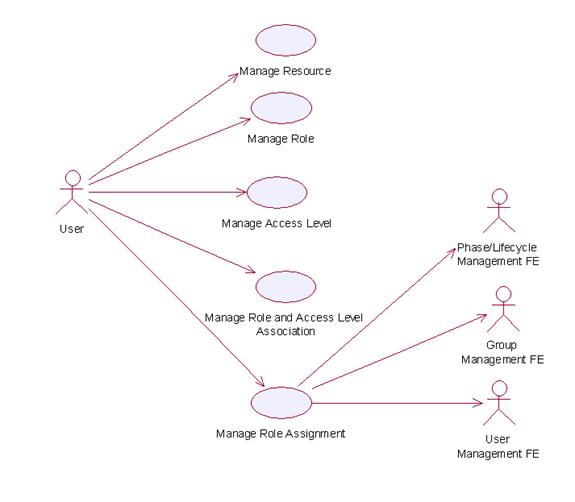
2.16.7Usage Scenario
2.16.7.1 Manage Role
2.16.7.1.1 Description
This use case allows the service user to manipulate the role information such as adding, changing and deleting role information in the Functional Element.
2.16.7.1.2 Flow of Events
2.16.7.1.2.1 Basic Flow
This use case starts when any user wants to create, change or delete a role.
1: Service user specifies the function it would like to perform (either create a role, update a role or delete a role).
2: Once the service user provides the requested information, one of the sub-flows is executed.
If the service user provides ‘Create a Role’, then sub-flow 2.1 is executed.
If the service user provides ‘Retrieve a Role’, then sub-flow 2.2 is executed.
If the service user provides ‘Update a Role’, then sub-flow 2.3 is executed.
If the service user provides ‘Delete a Role’, then sub-flow 2.4 is executed.
2.1: Create a Role.
2.1.1: The service user specifies role information such as the role name and description.
2.1.2: The Functional Element connects to the data storage.
2.1.3: The Functional Element checks whether the role exists in the Functional Element or not, saves the role information in the data storage and the use case ends.
2.2: Retrieve a Role.
2.2.1: The service user specifies the role name for retrieval.
2.2.2: The Functional Element connects to the data storage.
2.2.3: The Functional Element retrieves the role information in the data storage and the use case ends.
2.3: Update a Role.
2.3.1: The service user specifies the role name to update.
2.3.2: The service user specifies the target field name and value of the role.
2.3.3: The Functional Element connects to the data storage.
2.3.4: The Functional Element updates the role information in the data storage and the use case ends.
2.4: Delete a Role.
2.4.1: The service user specifies the role name to delete.
2.4.2: The Functional Element connects to the data storage.
2.4.3: The Functional Element removes the record of the role in the data storage and the use case ends.
2.16.7.1.2.2 Alternative Flows
1: Data Storage Not Available.
1.1: If in basic flow 2.1.2, 2.2.2, 2.3.3 and 2.4.2, the data storage of the role information is not available, an error message is returned and the use case ends.
2: Role Already Exists.
2.1: If in basic flow 2.1.3, the Functional Element checks that the role already exists in the data storage, an error message is returned and the use case ends.
3: Role Does Not Exist.
3.1: If in basic flow 2.2.3, 2.3.4 and 2.4.3, the Functional Element checks that the role does not exist in the data storage, an error message is returned and the use case ends.
4: Role Cannot Be Deleted.
4.1: If in basic flow 2.4.3, the other information associated with the role, such as any access level assigned, still exists, the role information may not be removed. An error message is returned and the use case ends.
2.16.7.1.3 Special Requirements
None
2.16.7.1.4 Pre-Conditions
None.
2.16.7.1.5 Post-Conditions
If the use case was successful, the role is saved/updated/removed in the Functional Element. Otherwise, the Functional Element state is unchanged.
2.16.7.2 Manage Resource
2.16.7.2.1 Description
This use case allows the service user to manipulate the resource information such as adding, changing and deleting resource information in the Functional Element.
2.16.7.2.2 Flow of Events
2.16.7.2.2.1 Basic Flow
This use case starts when any user wants to create, change or delete a resource.
1: The user specifies the function it would like to perform.
2: The user provides the requested information, one of the sub-flows is executed.
If the user provides ‘Create a Resource’, then sub-flow 2.1 is executed.
If the user provides ‘Retrieve a Resource’, then sub-flow 2.2 is executed.
If the user provides ‘Update a Resource’, then sub-flow 2.3 is executed.
If the user provides ‘Delete a Resource’, then sub-flow 2.4 is executed.
2.1: Create a Resource.
2.1.1: The user specifies resource information such as the resource name and description.
2.1.2: The Functional Element connects to the data storage.
2.1.3: The Functional Element checks whether the resource exists in the Functional Element, saves the resource information in the data storage and the use case ends.
2.2: Retrieve a Resource.
2.2.1: The service user specifies the resource name for retrieval.
2.2.2: The Functional Element connects to the data storage.
2.2.3: The Functional Element retrieves the resource information in the data storage and the use case ends.
2.3: Update a Resource.
2.3.1: The service user specifies the resource name to update.
2.3.2: The Functional Element connects to the data storage.
2.3.3: The Functional Element updates the resource information in the data storage and the use case ends.
2.4: Delete a Resource.
2.4.1: The service user specifies the resource name to delete.
2.4.2: The Functional Element connects to the data storage.
2.4.3: The Functional Element removes the record of the resource in the data storage and the use case ends.
2.16.7.2.2.2 Alternative Flows
1: Data Storage Not Available.
1.1: If in basic flow 2.1.2, 2.2.2, 2.3.2 and 2.4.2, the data storage of the resource information is not available, an error message is returned and the use case ends.
2: Resource Already Exists.
2.1: If in basic flow 2.1.3, the Functional Element checks that the resource already exists in the data storage, an error message is returned and the use case ends.
3: Resource Does Not Exist.
3.1: If in basic flow 2.2.3, 2.3.3 and 2.4.3, the Functional Element checks that the resource does not exist in the data storage, an error message is returned and the use case ends.
2.16.7.2.3 Special Requirements
None
2.16.7.2.4 Pre-Conditions
None.
2.16.7.2.5 Post-Conditions
None
2.16.7.3 Manage Access Level
2.16.7.3.1 Description
This use case allows service user to manage the creation/retrieval/modification/deletion of access level.
2.16.7.3.2 Flow of Events
2.16.7.3.2.1 Basic Flow
This use case starts when service user wants to manage the access levels.
1: The service user specifies the function it would like to perform (add, update or delete an access level).
2: Once the service user provides the requested information, one of the sub-flows is executed.
If the service user provides ‘Add an Access Level’, then sub-flow 2.1 is executed.
If the service user provides ‘Retrieve an Access Level’, then sub-flow 2.2 is activated.
If the service user provides ‘Update an Access Level’, then sub-flow 2.3 is activated.
If the service user provides ‘Delete an Access Level’, then sub-flow 2.4 is executed.
2.1: Add an Access Level.
2.1.1: The service user specifies the access level information, which includes: name, description, name of parent access level and group of resources that the access level is associated with.
2.1.2: The Functional Element connects to the data storage.
2.1.3: The Functional Element check whether the access level and its parent access level exist in the Functional Element, saves the access level information in the data storage and the use case ends.
2.2: Retrieve an Access Level.
2.2.1: The service user specifies the access level name to retrieve.
2.2.2: The Functional Element connects to the data storage.
2.2.3: The Functional Element gets access level information from the data storage and returns to the service user and the use case ends.
2.3: Update an Access Level.
2.3.1: The service user specifies the access level name.
2.3.2: The service user specifies the field(s) and new value(s) to update.
2.3.3: The Functional Element connects to the data storage.
2.3.4: The Functional Element updates the access level information in the data storage with the value specified in 2.3.2 and the use case ends.
2.4: Delete an Access Level.
2.4.1: The service user specifies the access level name to delete.
2.4.2: The Functional Element connects to the data storage.
2.4.3: The Functional Element removes the record of the access level in the data storage and the use case ends.
2.16.7.3.2.2 Alternative Flows
1: Data Storage Not Available.
1.1: If in basic flow 2.1.2, 2.2.2, 2.3.3 and 2.4.2, the data storage of the access level information is not available, an error message is returned and the use case ends.
2: Access Level Already Exists.
2.1: If in basic flow 2.1.3, the Functional Element checks that the access level already exists in the data storage, an error message is returned and the use case ends.
3: Access Level Cannot Be Deleted.
3.1: If in basic flow 2.4.3, the other information associated with the Access Level, such as roles to which the access level is assigned and the parent access level still exists, the access level information may not be removed. An error message is returned and the use case ends.
4: Parent Access Level Not Exist.
4.1: If in basic flow 2.1.3, the parent access level does not exist, an error message is returned and the use case ends.
2.16.7.3.3 Special Requirements
None
2.16.7.3.4 Pre-Conditions
None.
2.16.7.3.5 Post-Conditions
None
2.16.7.4 Manage Role and Access Level Association
2.16.7.4.1 Description
This use case allows service user to assign, update and remove the access level assigned to role.
2.16.7.4.2 Flow of Events
2.16.7.4.2.1 Basic Flow
This use case starts when service user wants to manage the relationship between access level and role.
1: The service user specifies a role and the function he/she would like to perform on the role (either assign an access level to role, update role access level, or delete role access level).
2: Once the service user provides the requested information, one of the sub-flows is executed.
If the user provides ‘Assign an Access Level to Role’, then sub-flow 2.1 is executed.
If the user provides ‘Update Access Level for Role’, then sub-flow 2.2 is executed.
If the user provides ‘Delete Access Level for Role’, then sub-flow 2.3 is executed.
If the user provides ‘Retrieve Access Level for Role’, then sub-flow 2.4 is executed.
If the service user provides ‘Retrieve Role for Access Level’, then sub-flow 2.5 is executed.
2.1: Assign an Access Level to Role.
2.1.1: The service user specifies access level that will be assigned to the role.
2.1.2: The Functional Element connects to the data storage.
2.1.3: The Functional Element checks whether the access level has been assigned to the role. Functional Element saves the access level reference in the role record in the data storage and the use case ends.
2.2: Update Access Level for Role.
2.2.1: The service user specifies the access level to update and the new access level information.
2.2.2: The Functional Element connects to the data storage.
2.2.3: The Functional Element updates the access level reference in the role record in the data storage and the use case ends.
2.3: Delete Access Level to Role.
2.3.1: The service user specifies the access level to delete.
2.3.2: The Functional Element connects to the data storage.
2.3.3: The Functional Element removes the access level reference from the record of the role in the data storage and the use case ends.
2.4: Retrieve Access Level for Role.
2.4.1: The service user specifies the role to retrieve the access levels associated with it.
2.4.2: The Functional Element connects to the data storage.
2.4.3: The Functional Element retrieves the access level assigned to the role in the data storage and the use case ends.
2.5: Retrieve Role for Access Level.
2.5.1: The service user specifies the access level to retrieve roles associated to it.
2.5.2: The Functional Element connects to the data storage.
2.5.3: The Functional Element retrieves roles associated to the access level in the data storage and the use case ends.
2.16.7.4.2.2 Alternative Flows
1: Data Storage Not Available.
1.1: If in basic flow 2.1.2, 2.2.2 and 2.3.2, the data storage of the access level information is not available, an error message is returned and the use case ends.
2: Access Level Assignment Already Exists.
2.1: If in basic flow 2.1.3, the Functional Element checks that the access level already exists in the role record in the data storage, an error message is returned and the use case ends.
3: Access Level Assignment Not Exist.
3.1: If in basic flow 2.3.3, the access level assignment does not exist, an error message is returned and the use case ends.
4: Access Level Not Exist.
4.1: If in basic flow 2.1.3, 2.2.3, 2.3.3, 2.4.3 and 2.5.3, the access level does not exist, an error message is returned and the use case ends.
5: Role Not Exist.
5.1: If in basic flow 2.1.3, 2.2.3, 2.3.3, 2.4.3 and 2.5.3, the role does not exist, an error message is returned and the use case ends.
2.16.7.4.3 Special Requirements
None.
2.16.7.4.4 Pre-Conditions
None.
2.16.7.4.5 Post-Conditions
None.
2.16.7.5 Manage Role Assignment
2.16.7.5.1 Description
The use case allows service user to assign a role to a user, a group, a phase in a lifecycle, to change or to delete such assignment.
2.16.7.5.2 Flow of Events
2.16.7.5.2.1 Basic Flow
This use case starts when the service user wants to manage the assignment of a role. This role can be assigned to a user, group, phase and lifecycle.
1: Service user specifies a role and an operation to perform on the role.
2: Once the service user provides the requested information, one of the sub-flows is executed.
If the user provides ‘Assign Role’, then sub-flow 2.1 is executed.
If the user provides ‘Retrieve Role’, then sub-flow 2.2 is executed.
If the user provides ‘Un-assign Role’, then user sub-flow 2.3 is executed.
2.1: Assign Role.
2.1.1: The service user specifies a user/group/phase/lifecycle to which the role will be assigned.
2.1.2: Depending of target of the assignment, the Functional Element will check for the presence of one of the following Functional Elements.
User Management Functional Element
Group Management Functional Element
Phase and Lifecycle Management Functional Element
2.1.3: The Functional Element checks whether the role has been assigned to the intended target
2.1.4: The Functional Element saves the relationship between the role and the target and the use case ends.
2.2: Retrieve Role.
2.2.1: The service user specifies a user/group/phase/lifecycle to retrieve all roles assigned
2.2.2: Depending of target of the assignment, the Functional Element will check for the presence of one of the following Functional Elements.
User Management Functional Element
Group Management Functional Element
Phase and Lifecycle Management Functional Element
2.2.3: The Functional Element gets the roles that are assigned to the target.
2.2.4: The Functional Element returns the results to the service user and the use case ends.
2.3: Un-assign Role.
2.3.1: The service user specifies a user/group/phase/lifecycle and the role that is to be un-assigned.
2.3.2: Depending of target of this un-assignment, the Functional Element will check for the presence of one of the following Functional Elements.
User Management Functional Element
Group Management Functional Element
Phase and Lifecycle Management Functional Element
2.3.3: The Functional Element checks if the roles have been assigned to the target in the first place.
2.3.4: The Functional Element removes the role assigned and the use case ends.
2.16.7.5.2.2 Alternative Flows
1: Dependent Functional Element not available.
1.1: If in basic flow 2.1.2, 2.2.2 and 2.3.2, the dependent Functional Elements are not available, an error message is returned and the use case ends.
2: Invalid User/Group/Phase/Lifecycle Account.
2.1: If in basic flow 2.1.2, 2.2.2 and 2.3.2, the dependent Functional Elements are available but an invalid account is provided, an error message is returned and the use case ends.
3: Data Storage Not Available.
3.1: If in basic flow 2.1.2, 2.2.2 and 2.3.2, the Functional Element is unable to access the data storage, an error message is provided and the use case ends.
2.16.7.5.3 Special Requirements
None.
2.16.7.5.4 Pre-Conditions
None.
2.16.7.5.5 Post-Conditions
None.
2.17 Search Functional Element
2.17.1Motivation
In a Web Service-enabled implementation, information is distributed across different sites and this makes searching and collating information difficult. Against this backdrop, this Functional Element is expected to fulfill the needs identified within an application by covering the following aspects.
Providing the capability for configuration of different types of data sources for information search,
Providing the facility to provide a concrete definition of data source classification for information search
,
Providing the ability to define different search scopes for various data source classification
,
Performing information search on those pre-configured different types of data sources and
Providing the provision to consolidate the return result arising from the search operation.
This Functional Element fulfills the following requirements from the Functional Elements Requirements, Working Draft 01a:
Primary Requirements
·
MANAGEMENT-009,
·
PROCESS-030 to PROCESS-031, and
·
PROCESS-034.
Secondary Requirements
·
None
2.17.2Terms Used
|
Terms |
Description |
|
Data source |
Data source refers to any kind of information storage and retrieval databases like RDBMS, LDAP, ODBMS, XMLDB, XML Files, TEXT Files, etc. |
|
Search Category |
A
Search Category refers to some logical grouping of the data sources on the
basis of purpose of various data source purpose like NE |
|
Data Source Type |
Data Source Type refers to the various kinds of data storage format or structure like XML, HTML, TEXT, Databases, Tables, Rows, Columns in RDBMS, Collections, Nodes, Files & Tags in XMLDB, that are used to store and retrieve information from different data sources |
|
RDBMS |
Relational Database Management Systems |
|
XMLDB |
eXtensible Markup Language (XML) Database |
|
LDAP |
Lightweight Directory Access Protocol |
|
XML |
eXtensible
Markup Language |
|
HTML |
HyperText Markup
Language |
2.17.3Key Features
Implementations of the Search Functional Element are expected to provide the following key features:
1. The Functional Element MUST provide a mechanism to define and manage Search Categories.
2. The Functional Element MUST provide the capability to configure and store information about targeted data sources for a particular Search Category.
Example:
Some of the stored information would include Location, Type, Name, Data Fields
(of interest to the search) and access control (typically username and
password) of the targeted data source.
3. As part of Key Feature (2), the Functional Element MUST also provide the ability to configure the scope of search and returned results.
4. The Functional Element MUST also provide a mechanism to link the Search Categories to configured target data sources.
5. The Functional Element MUST provide the ability to search multiple data sources for a defined Search Category.
Example: Some of the common data sources
would include RDBMS, XML DB, LDAP servers and flat files like XML files, text
files and HTML files
6. The Functional Element MUST provide the ability to perform searches based on a given set of keyword(s).
In addition, the following key features could be provided to enhance the Functional Element further:
1. The Functional Element MAY also provide the ability to perform conditional and parametric searches.
2. The Functional Element MAY also provide the ability to restrict the scope of a search.
Example: By
providing a particular Search Category or types of data sources for the search.
2.17.4Interdependencies
None
2.17.5Related Technologies and Standards
None
2.17.6Model
|
|
2.17.7Usage Scenario
2.17.7.1 Manage Search Categories
2.17.7.1.1 Description
This use case allows the users to manage the different search categories.
2.17.7.1.2 Flow of Events
2.17.7.1.2.1 Basic Flow
This use case starts when the user wishes to manage the different data sources for search to be performed on it.
1: The users initiates a request to configure data source(s) and type(s) by providing the data source information and type to be added, removed or retrieved.
2: The Functional Element checks whether the data source configuration file exists.
3: The Functional Element checks the request. Based on the type of request, one of the sub-flows is executed.
If the request is to ‘Create Data Source And Type’, then sub-flow 3.1 is executed.
If the request is to ‘View Data Sources And Types’, then sub-flow 3.2 is executed.
If the request is to ‘Delete Data Source And Type’, then sub-flow 3.3 is executed.
3.1: Create Data Source and Type.
3.1.1: The Functional Element checks whether the same data source and type has been created.
3.1.2: The Functional Element appends the new data source and type in the data source configuration file specified.
3.2: View Data Source and Type.
3.2.1: The Functional Element retrieves all the data source and type information from the data source configuration file.
3.2.2: The Functional Element returns the data source(s) and type(s).
3.3: Delete Data Source and Type.
3.3.1: The Functional Element checks whether the data source and type exist in the data source configuration based on data source id from the data source configuration file.
3.3.2: The Functional Element removes the old data source and type from the data source configuration file.
4: The Functional Element returns a success or failure flag indicating the status of the operation being performed and use case ends.
2.17.7.1.2.2 Alternative Flows
1: Data Source Configuration File Not Found.
1.1: If in basic flow 2, the data source configuration file does not exist, the Functional Element creates an empty data source configuration file.
2: Duplicate Data Source and Type.
2.1: If in basic flow 3.1.1, the same data source and type have been configured, the Functional Element returns an error message and the use case end.
3: Data Source and Type Do Not Exist.
3.1: If in basic flow 3.2.1 and 3.3.1, a particular data source and type cannot be found in the specified data source configuration file, the Functional Element returns an error message and the use case end.
2.17.7.1.3 Special Requirements
None.
2.17.7.1.4 Pre-Conditions
None.
2.17.7.1.5 Post-Conditions
None.
2.17.7.2 Search Information
2.17.7.2.1 Description
This use case allows any users to perform search on various disparate data sources and types configured to be searched and returns the matching results.
2.17.7.2.2 Flow of Events
2.17.7.2.2.1 Basic Flow
This use case starts when users wishes to perform information search on a data source.
1: Users initiates a request to perform information search on a given data source by providing information to be searched, location of the data source(s) and the data source type(s).
2: The Functional Element checks for the existence of the specified data source(s).
3: The Functional Element validates the data source type(s) against the set of supported data type(s) configured within the Functional Element that are available for information search.
4: The Functional Element performs information search based on the search parameters given by the users or the other Functional Elements.
5: The Functional Element returns the result of the information search performed to the users or other Functional Elements and use case ends.
2.17.7.2.2.2 Alternative Flows
1: Data Source(s) Are Not Available.
1.1: In basic flow 2, if the identified data source is not available, the Functional Element returns an error message and the use case ends.
2: Invalid Configuration Instructions
2.1: In basic flow 2, if the input inform by the user is incomplete, the Functional Element returns an error message and the use case ends.
3: Invalid Data Source Type.
3.1: In basic flow 3, if the data source type is invalid, the Functional Element returns an error message and the use case ends.
4: No Matching Result.
4.1: In basic flow 4, if the search results in no matching results, the Functional Element returns an error message and the use case ends..
2.17.7.2.3 Special Requirements
None
2.17.7.2.4 Pre-Conditions
None.
2.17.7.2.5 Post-Conditions
None.
2.18 Secure SOAP Management Functional Element
2.18.1Motivation
In a Web Services implementation, it is envisage that confidential information is being exchanged all the time. Against this backdrop, it is imperative that an application in such an environment is equipped with the capability to guard sensitive information from prying eyes. Secure SOAP Management fulfills this need by covering the following areas.
The facility of digitally signing SOAP message,
The facility of encrypting SOAP message, and
The capability to generate the original SOAP message after signing or encrypting the message.
This Functional Element fulfills the following requirements from the Functional Elements Requirements, Working Draft 01a:
Primary Requirements
·
SECURITY-003 (SECURITY-003-3 only),
·
SECURITY-020 (all), and
·
SECURITY-022, and
·
SECURITY-026.
Secondary Requirements
·
None
2.18.2Terms Used
|
Terms |
Description |
|
Digital Signature |
An
electronic signature that can be used to authenticate the identity of the
sender of a message, or of the signer of a document. It can also be used to
ensure that the original content of the message or document that has been
conveyed is unchanged |
|
Encryption |
A
method of scrambling or encoding data to prevent unauthorized users from
reading or tampering with the data. Only individuals with access to a
password or key can decrypt and use the data. |
|
PKCS#11 |
The cryptographic token interface standards. Defines a technology independent programming interface for cryptographic devices such as smart cards. |
|
Public Key Cryptography Specification ( PKCS) #12 |
The personal information exchange syntax standard. Defines a potable format for storage and transportation of user private keys, certificates etc. |
2.18.3Key Features
Implementations of the Secure SOAP Functional Element are expected to provide the following key features:
1. The Functional Element MUST provide the capability to digitally sign SOAP messages completely or partially using XML-Signature Syntax and Processing, W3C Recommendation 12 February 2002.
2. The Functional Element MUST provide the capability to validate a signed SOAP message.
3. The Functional Element MUST provide the capability to encrypt SOAP messages completely or partially using XML-Encryption Syntax and Processing, W3C Recommendation 10 December 2002.
4. The Functional Element MUST provide the capability to decrypt encrypted SOAP messages.
5. The Functional Element MUST support PKCS12 compatible digital certificates.
6. The Functional Element MUST be able to verify the validity and authenticity of digital certificates used.
In addition, the following key features could be provided to enhance the Functional Element further:
1. The Functional Element MAY also support PKCS11 compatible tokens.
2. The Functional Element MAY also provide log support as part of the audit trails for its transaction records.
2.18.4Interdependencies
|
Direct
Dependency |
|
|
Log Utility Functional Element |
The Log Utility Functional Element is being used for logging and creation of audit trails. |
2.18.5Related Technologies and Standards
|
Standards / Specifications |
Specific References |
|
Public Key Infrastructure (PKI) |
PKI
is a system of digital certificates, Certificate Authorities, and other
registration authorities that verify and authenticate the validity of each
party involved in an Internet transaction In this Functional Element, the private key and public key are generated for the Functional Element to sign and encrypt SOAP messages. The Functional Element uses the session key to encrypt the SOAP message. The digital certificate is attached to the SOAP message after the Functional Element has signed the SOAP message. |
|
XML-Signature
Syntax and Processing, W3C Recommendation |
This
specification addresses authentication, non-repudiation and data-integrity
issues. In addition, it also specifies the XML
syntax and processing rules for creating and representing digital signatures. In this Functional Element, both the digital signature on the SOAP message and validation of the signed SOAP message is done based on this specification. |
|
XML-Encryption
Syntax and Processing, W3C Recommendation [[18]] |
This specification addresses data privacy by defining a process for encrypting data and representing the result in XML document. In this Functional Element, the encryption and decryption of SOAP messages are done based on this specification. |
2.18.6Model
|
|
|
Figure 24: Model Of the Secure SOAP Management Functional Element [[19]] |
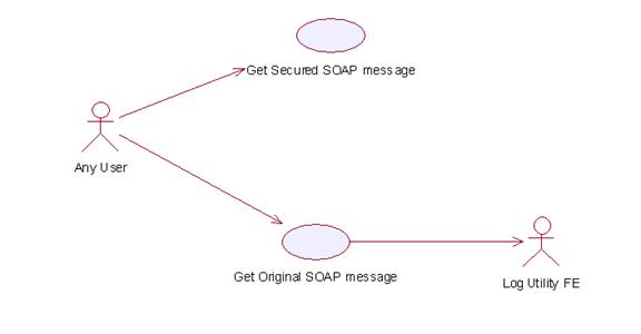
2.18.7Usage Scenarios
2.18.7.1 Get Secured SOAP message
2.18.7.1.1 Description
This Functional Element describes the process to generate secured SOAP message.
2.18.7.1.2 Flow of Events
2.18.7.1.2.1 Basic Flow
This use case starts when the user wants to secure the SOAP message.
If user wants to ‘Sign SOAP message’, then basic flow 1 is executed.
If user wants to ‘Encrypt and Sign the SOAP message’, then basic flow 2 is executed.
1: Sign SOAP Message.
1.1: User sends the SOAP message, digital certificate and specifies the element name that needs to be signed.
1.2: Functional Element gets the key information from the digital certificate.
Note:
The private key will be used to sign the SOAP message and the public key will
be added to the SOAP message after the signing.
1.3: Functional Element signs the element.
Note:
The digital signature format is expected to be based on XML-Digital Signature
Syntax mentioned in section 3.10.5.
1.4: Functional Element parses the secure SOAP message and regenerates the SOAP message.
1.5: Functional Element returns the secured SOAP message to user and the use case ends.
2: Encrypt And Sign SOAP Message.
2.1: User sends the SOAP message, digital certificate and specify the element name that needs to be encrypted.
2.2: User sends the receiver’s public key information to Functional Element.
Note:
Receiver’s public key will be used to encrypt the session key, which was then
used to encrypt the content of the element in the SOAP message.
2.3: Functional Element gets key information from the user’s digital certificate.
Note:
Private key is used to sign the SOAP message and public key is used to add into
the SOAP message after the signing.
2.4: Functional Element generates the session key.
Note:
Session key is used to encrypt the content of the element.
2.5: Functional Element encrypts the content of element with the session key.
2.6: Functional Element encrypts session key with the receiver’s public key.
2.7: Functional Element signs the SOAP message after encryption.
2.8: Functional Element regenerates the SOAP message.
Note:
Functional Element adds the encrypted content of the element, encrypted session
key information, the receiver’s public key information and the signature to the
SOAP message.
2.9: Functional Element returns the SOAP message and the use case ends.
2.18.7.1.2.2 Alternative Flows
1: Cannot Get Key.
1.1: In basic flow 1.2 and 2.3, Functional Element cannot get the key information from the digital certificate. The Functional Element returns an error message and the use case ends.
2: Cannot Sign
2.1: In basic flow 1.3, Functional Element cannot sign the SOAP message. The Functional Element returns an error message and the use case ends.
3: Cannot Encrypt
3.1: In basic flow 2.5, Functional Element cannot encrypt the SOAP message. The Functional Element returns an error message and the use case ends.
2.18.7.1.3 Special Requirements
None.
2.18.7.1.4 Pre-Conditions
None.
2.18.7.1.5 Post-Conditions
None.
2.18.7.2 Get Original SOAP Message
2.18.7.2.1 Description
This use case allows users to get original SOAP message.
2.18.7.2.2 Flow of Events
2.18.7.2.2.1 Basic Flow
This use case starts when the user wants to get the original SOAP message.
If the user wants to ‘Verify the SOAP message’, then basic flow 1 is executed.
If the user wants to ‘Decrypt and Verify the SOAP message’, then basic flow 2 is executed.
1: Verify SOAP Message.
1.1: User sends the SOAP message and sender’s digital certificate.
1.2: Functional Element verifies the SOAP message.
Note:
The sender’s certificate information will be used to verify the signature.
1.3: Functional Element gets the original SOAP message, returns to user and the use case ends.
2: Decrypt And Verify The SOAP Message.
2.1: User sends the SOAP message, user’s digital certificate and sender’s certificate.
2.2: Functional Element verifies the SOAP message.
Note:
The sender’s certificate information will be used to verify the signature.
2.3: Functional Element gets the user’s key information from the user’s digital certificate.
Note:
The user’s private key will be used to decrypt the session key.
2.4: Functional Element decrypts the session key.
2.5: Functional Element decrypts the content of the element with the session key.
2.6: Functional Element regenerates the SOAP message.
Note:
Functional Element removes the session key information and the digital
signature information from the SOAP message and gets the original one.
2.7: Functional Element returns the original SOAP message to user and the use case ends.
2.18.7.2.2.2 Alternative Flows
1: Verification Fails.
1.1: In basic flow 1.3 and 2.3, if verification fails, the Functional Element returns an error message and the use case ends.
2: Decryption of Content Fails.
2.1: In basic flow 2.5, the Functional Element cannot decrypt the content of the element. The Functional Element returns an error message and the use case ends.
2.18.7.2.3 Special Requirements
None
2.18.7.2.4 Pre-Conditions
None.
2.18.7.2.5 Post-Conditions
None.
2.19 Sensory Functional Element
2.19.1Motivation
In a Web Service implementation where the presentation capabilities of clients differ, there is a need to determine the exact ability of the end devices so that the appropriate contents may be forwarded. The Sensory Functional Element can help to play this role by covering the following aspects within an application:
Determining the presentation capabilities by inspecting incoming headers, and
Determining the presentation capabilities by extracting MIME information from the relevant headers.
Primary Requirements
·
DELIVERY-001,
·
DELIVERY-005 to DELIVERY-006, and
·
DELIVERY-009.
Secondary Requirements
·
MANAGEMENT-011, and
·
MANAGEMENT-096.
2.19.2Terms Used
|
Terms |
Description |
|
HTTP |
Hyper Text Transport Protocol [HTTP]
refers to the protocol for moving hypertext files across the Internet.
Requires a HTTP client program on one end, and an HTTP server program on the
other end. HTTP is the most important protocol used in the World Wide Web
(WWW). |
|
MIME |
Multipurpose Internet Mail Extensions
(MIME) refers to a standard that allows the embedding of arbitrary
documents and other binary data of known types (images, sound, video, and so
on) into e-mail handled by ordinary Internet electronic mail interchange
protocols |
|
Location Based Services (LBS) |
Location-based
services (LBS) refer to the services that provides users of mobile devices
personalized services tailored to their current location. |
2.19.3Key Features
Implementations of the Sensory Functional Element are expected to provide the following key features:
1. The Functional Element MUST intercept HTTP requests from client and determines existing supportability of the request’s MIME type.
2. The Functional Element MUST provide the mechanism to manage MIME types, including the ability to add, delete and retrieve supported MIME types.
In addition, the following key features could be provided to enhance the Functional Element further:
1. The Functional Element MAY provide a mechanism to enable Location Based Services (LBS).
2.19.4Interdependencies
|
|
|
|
Presentation Transformer Functional Element |
The Presentation Transformer Functional Element may be used to generate the appropriate output for the targeted devices. |
2.19.5Related Technologies and Standards
None.
2.19.6Model
|
|
2.19.7Usage Scenarios
2.19.7.1 Detect Supported Format
2.19.7.1.1 Description
This use case allows the service user (user/other service) to make request and based on that request it detects service user’s device capabilities.
2.19.7.1.2 Flow of Events
2.19.7.1.2.1 Basic Flow
This use case starts when the service user wishes to use any service provided by the service provider.
1: The Functional Element receives the request from the service user.
2: The Functional Element extracts MIME name and MIME type from the service user’s HTTP request (even from SOAP request).
3: The Functional Element uses MIME name and MIME TYPE to check with the pre-registered MIME type.
4: The Functional Element sends device capabilities to service user and ends the use case.
2.19.7.1.2.2 Alternative Flows
1: Unsupported Device.
1.1 If in the basic flow 2, the Functional Element is unable to detect the service user’ device capability, the Functional Element returns a error message and the use case ends.
2.19.7.1.3 Special Requirements
None
2.19.7.1.3.1 Supportability
The edge devices must be able to support the HTTP request.
2.19.7.1.4 Pre-Conditions
None.
2.19.7.1.5 Post-Conditions
None.
2.19.7.2 Manage Device Types
2.19.7.2.1 Description
This use case allows the service user to maintain the device (MIME Type information). This includes adding, changing and deleting device information from the Functional Element.
2.19.7.2.2 Flow of Events
2.19.7.2.2.1 Basic Flow
This use case starts when the service user wishes to add or delete either device or service information from the Functional Element.
1: The Functional Element requests that the service user specify the function to perform (either add, update or delete device or service).
2: Once the service user provides the requested information, one of the sub-flows is executed.
If the service user provides ‘Register Device Types’, then sub-flow 2.1 is executed.
If the service user provides ‘Delete Device Types’, then sub-flow 2.2 is executed.
2.1: Register Device Type.
2.1.1: The Functional Element requests that the service user provide the device information. This includes: MIME Name, MIME Description, Supported MIME type.
2.1.2: Once the service user provides the requested information, the Functional Element generates and assigns a unique MIME Id number to the device.
2.2: Delete Device Type.
2.2.1: The Functional Element requests that the service user provide the Device ID.
2.2.2: The Functional Element retrieves the existing device information based on the Device ID.
2.2.3: The service user provides the delete device information and the Functional Element deletes the device record from the Functional Element.
3: The use case ends when the service user provides the requested information or decided to end use case.
2.19.7.2.2.2 Alternative Flows
1: Invalid Device Information.
1.1: If in the sub-flow 2.1.2, the requested information provided by the user is invalid, the Functional Element returns an error message and the use case ends
2: Device Not Found.
2.1 If in the basic flows 2.2.2, the device information with the specified device is not found or does not exist, the Functional Element returns an error message and the use case ends.
2.19.7.2.3 Special Requirements
2.19.7.2.3.1 Supportability
Manage Device Types supports the most widespread MIME types used today.
2.19.7.2.4 Pre-Conditions
None.
2.19.7.2.5 Post-Conditions
If the use case was successful, the device information is added, updated or deleted from the Functional Element. Otherwise, the Functional Element’s state is unchanged.
2.20 Service Level Management Functional Element (new)
2.20.1 Motivation
The
Service Level Management Functional Element enables the management of Service Level Agreements (SLAs), each of
which represents a joint agreement
between the service customer and provider based on a set of service
offerings. The service offerings
typically expressed as
This Functional Element fulfills the following requirements from the Functional Elements Requirements:
Primary Requirement
·
MANAGEMENT-300.
2.20.2 Terms Used
|
Terms |
Description |
|
|
Service
Level Agreement is a joint agreement between service provider and service
customer to define a set of service offerings. |
2.20.3 Key Features
Implementations of the Service Level Management Functional Element are expected to provide the following key features:
1. The Functional Element MUST provide the ability to create Service Offering and associated service levels.
2. The Functional Element MUST provide the ability to manage defined Service Offerings, including the ability to retrieve, modify and delete.
3. The
Functional Element MUST provide the ability to create of a
4. The Functional Element MUST provide the ability to generate billing & service level reports based on defined SLAs.
5. The
Functional Element MUST provide the ability to notify subscribers of
6. The Functional Element MUST provide the ability to delete SLAs upon termination.
In addition, the following key features could be provided to enhance the Functional Element further:
1. The Functional Element MAY provide the ability to customize SLAs. This includes the capability to:
1.1. Alter service offerings parameters.
1.2. Add
and delete different service offerings into a
2.20.4 Interdependencies
|
Interaction
Dependencies |
|
|
QoS Management |
The Service Level Management Functional Element may make use of the metrics and metering results to model SLAs. |
|
Notification |
The Service Level Management Functional Element may make use of the Notification Functional Element to notify subscribers of certain SLAs the happening on the SLAs. |
2.20.5 Related Technologies and Standards
|
Standards / Specifications |
Specific References |
|
Web Service Level Agreement Project |
– Under IBM Emerging Technology Toolkit. Latest update was in 2003. No news on its standardization. |
2.20.6Model
|
|
|
Figure 26: Model of the Service Level Management Functional Element. |
2.20.7Usage Scenarios
2.20.7.1 Manage Service Offering
2.20.7.1.1 Description
This use case allows any user to manage service offering, which enables any user to create, retrieve, update and delete a service offering.
2.20.7.1.2 Flow of Events
2.20.7.1.2.1 Basic Flow
This use case starts when any user wants to manage service offerings.
1: The user sends Manage Service Offering request to the system together with the specified operation.
2: On receipt of the request from the user, the functional element will execute one of the sub-flows. If the service user provides “Create Service Offering”, the Create Service Offering sub-flow (2.1) is executed. If the service user provides “Update Service Offering”, the Update Service Offering sub-flow (2.2) is activated. If the service user provides “Retrieve Service Offering”, the Retrieve Service Offering sub-flow (2.3) is activated. If the service user provides “Delete Service Offering”, the Delete Service Offering sub-flow (2.4) is executed.
2.1: Create Service Offering.
2.1.1: The service user specifies details of a service offering.
2.1.2: The system checks the existing service offering.
2.1.3: The system generates service offering information and adds to the system and the use case ends.
2.2: Update Service Offering.
2.2.1: The service user specifies the service offering to update.
2.2.2: The system retrieves the existing service offering information.
2.2.3: The service user provides the update service offering information.
2.2.4: The system updates the service offering with the updated information and ends use case.
2.3: Retrieve Service Offering.
2.3.1: The service user specifies the service offering to retrieve.
2.3.2: The system retrieves the existing service offering information and ends the use case.
2.4: Delete Service Offering.
2.4.1: The service user
specifies the service offering to delete.
2.4.2: The system retrieves the existing service offering information.
2.4.3: The system deletes the service offering from the system and the use case ends.
2.20.7.1.2.2 Alternative Flows
1: Invalid Service Offering.
1.1: If in the Basic Flow 2.1.1, system detects any invalid description, system returns general error message and ends the use case.
2: Service Offering Already Exists.
2.1: If in the Basic Flow 2.1.2, the system checks the existing service offering and finds the service offering already exists. The system returns an error and ends the use case.
3: Service Offering Not Exist.
3.1: If in the Basic Flow 2.2.2, 2.3.2, 2.4.2, the system checks the existing service offering and finds the service offering doesn’t exist. The system returns an error and ends the use case.
2.20.7.1.3 Special Requirements
2.20.7.1.4 Pre-Conditions
None.
2.20.7.1.5 Post-Conditions
None.
2.20.7.2
Create SLA
2.20.7.2.1 Description
This use case allows any user to create Service Level Agreement.
2.20.7.2.2 Flow of Events
2.20.7.2.2.1 Basic Flow
This use case starts when
any user wants to create
1: The user sends a
request to create
2:
The Functional Element will dispatch the
3:
The subscribers accept the
2.20.7.2.3 Alternative Flows
1: Service Offering Not Available.
1.1: If in the Basic Flow 1, Functional Element detects the service offering provided by the user is not available, the Functional Element returns general error message and ends the use case.
2: Subscriber Not Available.
2.1: If in the Basic Flow 2, the Functional Element checks that the subscriber is not available, the Functional Element returns an error and ends the use case.
3: Subscriber Don’t Agree.
3.1:
If in the Basic Flow 3, the subscriber does not agree with the arrangement
defined in
2.20.7.2.4 Special Requirements
None.
2.20.7.2.5 Pre-Conditions
None.
2.20.7.2.6 Post-Conditions
If
the use case is successful, a
2.20.7.3 Perform Billing and Reporting
This
use case allows any user to do billing and reporting of the information related
to
2.20.7.3.1 Flow of Events
2.20.7.3.1.1 Basic Flow
This use case starts when
any user wants to do
1: The user sends a
request to conduct billing and reporting by providing information, which
enables to identify the
2: On receipt of request
of performing billing and reporting from the user, the Functional Element
retrieves the billing and report information according to the definition of
3: The Functional Element passes the generated information to the subscribers.
4: The Functional Element passes the response to the user and the use case ends.
2.20.7.3.1.2 Alternative Flows
1: Information Not Enough.
1.1:
If in the Basic Flow 1, Functional Element detects the information provided by
the user is not enough to form identify the
2: No Data Available.
2.1: If in the Basic Flow 2, the Functional Element retrieves the recorded information and finds it is unavailable or incomplete, the Functional Element returns an error and ends the use case.
3: Subscriber Not Available.
3.1: If in the Basic Flow 3, the subscriber is not available, the Functional Element returns an error and ends the use case.
2.20.7.3.2 Special Requirements
None.
2.20.7.3.3 Pre-Conditions
None.
2.20.7.3.4 Post-Conditions
None.
2.20.7.4
Customize SLA
2.20.7.4.1 Description
This
use case allows users to customize a
2.20.7.4.1.1 Basic Flow
This use case starts when
any user wants to customize a
1: The user sends request
to customize a
2: On receipt of a
customizing
3: The Functional Element
passes the customized
4: The subscribers accept
the customized
5: The Functional Element passes the response from the service to the user and the use case ends.
2.20.7.4.1.2 Alternative Flows
1:
1.1:
If in the Basic Flow 1, the
2: Information Not Valid.
2.1:
If in the Basic Flow 2, Functional Element detects the information provided by
the user is not valid to form a
3: Subscriber Not Available.
3.1: If in the Basic Flow 3, the subscriber is not available, Functional Element returns general error message and ends the use case.
4: Subscriber Does Not Accept.
4.1:
If in the Basic Flow 4, the subscriber does not accept the customized
2.20.7.4.2 Special Requirements
None.
2.20.7.4.3 Pre-Conditions
None.
2.20.7.4.4 Post-Conditions
If
the use case is successful, a customized
2.20.7.5
Terminate SLA
This
use case enables the user to terminate a
2.20.7.5.1 Flow of Events
2.20.7.5.1.1 Basic Flow
This use case starts when
the user wants to terminate a
1: The user sends a
request to terminate a
2: On receipt of a
terminating
3: The Functional Element
notifies the subscribers about the termination of the
4: The Functional Element passes the response from the service to the user and the use case ends.
2.20.7.5.1.2 Alternative Flows
1:
1.1:
If in the Basic Flow 2, Functional Element detects the
2: Notification FE Not Available.
2.1: If in Basic Flow 3, Functional Element detects the Notification Functional Element is not available, Functional Element returns general error message and ends the use case.
2.20.7.5.2 Special Requirements
None.
2.20.7.5.3 Pre-Conditions
None.
2.20.7.5.4 Post-Conditions
If
the use case is successful, the Functional Element stops all the operations
related to the
2.20.7.6
Delete SLA
This
use case enables the user to remove a
2.20.7.6.1 Flow of Events
2.20.7.6.1.1 Basic Flow
This use case starts when
the user wants to delete a
1: The user sends a
request to delete a
2: On receipt of request
of deleting
3: The Functional Element
deletes the
4: The Functional Element passes the response from the service to the user and the use case ends.
2.20.7.6.1.2 Alternative Flows
1:
1.1:
If in the Basic Flow 2, Functional Element detects the
2: Terminate
2.1: If in the Basic Flow 2, use case Terminate SLA returns error, Functional Element returns general error message and ends the use case.
2.20.7.6.2 Special Requirements
None.
2.20.7.6.3 Pre-Conditions
None.
2.20.7.6.4 Post-Conditions
If
the use case is successful, a
2.21 Service Level Enforcement Functional Element (new)
2.21.1 Motivation
The
Service Level Enforcement Functional Element enables monitoring the compliance of
This Functional Element fulfills the following requirements from the Functional Elements Requirements:
· Primary Requirements
·
MANAGEMENT-301 and
·
MANAGEMENT-302.
2.21.2 Terms Used
|
Terms |
Description |
|
|
Service
Level Agreement is a joint agreement between service provider and service
customer to define a set of service offerings. |
2.21.3 Key Features
Implementations of the Service Level Enforcement Functional Element are expected to provide the following key features:
1.
The Functional Element MUST provide the ability
to monitor
2.
The Functional Element MUST provide the ability
to detect any violation of
3.
The Functional Element MUST provide the ability
to enforce a
In addition, the following key features could be provided to enhance the Functional Element further:
1. The Functional Element MAY provide the ability to manage load. This include the capability to:
1.1. Control admission of service.
1.2. Prioritize requests.
2.21.4 Interdependencies
|
Interaction
Dependencies |
|
|
QoS Management |
The
Service Level Enforcement Functional Element may make use the metrics and
metering results to monitor compliance of |
2.21.5 Related Technologies and Standards
|
Standards / Specifications |
Specific References |
|
Web Service Level Agreement Project |
– Under IBM Emerging Technology Toolkit. Latest update was in 2003. No news on its standardization. |
2.21.6 Model
|
|
|
Figure 27: Model of the Service Level Enforcement Functional Element. |
2.21.7Usage Scenarios
2.21.7.1
Monitor SLA Compliance
2.21.7.1.1 Description
This
use case allows any user to monitor and check the
2.21.7.1.2 Flow of Events
2.21.7.1.2.1 Basic Flow
This use case starts when
any user wants to monitor the
1: The user sends Monitor
SLA Compliance request to the Functional Element together with the specified
2: On
receipt of the request from the user, the Functional Element will retrieve the
3: The Functional Element extracts the measured data through QoS Management Functional Element.
4:
The Functional Element checks the compliance of
5: The Functional Element returns response to the user and the use case ends.
2.21.7.1.2.2 Alternative Flows
1:
1.1:
If in the Basic Flow 2, the Functional Element detects that the
2: Measured Data Not Available.
2.1: If in the Basic Flow 3, the Functional Element retrieves measured data through QoS Management Functional Element and the latter is not ready, the Functional Element returns an error and ends the use case.
3:
3.1:
If in the Basic Flow 4, the Functional Element checks the measured data against
2.21.7.1.3 Special Requirements
2.21.7.1.4 Pre-Conditions
None
2.21.7.1.5 Post-Conditions
None
2.21.7.2 Control Admission
2.21.7.2.1 Description
As a
means of manage load to enforce
2.21.7.2.2 Flow of Events
2.21.7.2.2.1 Basic Flow
This use case starts when any user wants to control admission toward services.
1: The user sends request to control admission to certain services to the Functional Element which includes the option of admission and the targeted services.
2: The Functional Element will manage the control of admission to the services at run time.
3: The Functional Element returns response to the user and the use case ends.
2.21.7.2.3 Alternative Flows
1: Service Not Available.
1.1: If in the Basic Flow 1, Functional Element detects the targeted service provided by the user is not available, Functional Element returns general error message and ends the use case.
2: Control Admission Failed.
2.1: If in the Basic Flow 2, the Functional Element fails to control admission to the services at run time, Functional Element returns an error and ends the use case.
2.21.7.2.4 Special Requirements
None.
2.21.7.2.5 Pre-Conditions
The services are manageable to the user.
2.21.7.2.6 Post-Conditions
If
the use case is successful, the load of the monitored services is changed thus
the
2.21.7.3 Prioritize Request
As a
means of load management to enable
2.21.7.3.1 Flow of Events
2.21.7.3.1.1 Basic Flow
This use case starts when any user wants to prioritize various requests to targeted services.
1: The user sends request to prioritize request to the Functional Element, which include information of the targeted services, the priority of the request and so on.
2: On receipt of the request from the user, the Functional Element controls the processing of the request according to the priority given at the run time.
3: The Functional Element passes the response to the user and the use case ends.
2.21.7.3.1.2 Alternative Flows
1: Services Not Exist.
1.1: If in the Basic Flow 1, Functional Element detects the targeted service provided by the user does not exist, Functional Element returns general error message and ends the use case.
2: Prioritize Request Fails.
2.1: If in the Basic Flow 2, the Functional Element fails to control the requests of the services according to the priority given the user, the Functional Element returns an error and ends the use case.
2.21.7.3.2 Special Requirements
None.
2.21.7.3.3 Pre-Conditions
The services are manageable to the user.
2.21.7.3.4 Post-Conditions
If
the use case is successful, the load of the monitored services is changed thus
the
2.21.7.4
Enforce SLA
2.21.7.4.1 Description
This
use case allows users to enforce a
2.21.7.4.1.1 Basic Flow
This use case starts when
any user wants to enforce a
1: The user sends a
request to enforce a
2: On receipt of the
request from the user, the Functional Element checks the
3: The Functional Element dispatches its request of load management and invokes use case Control Admission or use case Prioritize Request.
4: The Functional Element returns the response to the user and the use case ends.
2.21.7.4.1.2 Alternative Flows
1:
1.1:
If in the Basic Flow 1, the
2: Services Not Exist.
2.1:
If in the Basic Flow 1, Functional Element detects the services that the user
wants to enforce
3: Control Admission Not Working.
3.1: If in the Basic Flow 3, Functional Element fails to invoke use case control admission, Functional Element returns general error message and ends the use case.
4: Prioritize Request Not Working.
4.1: If in the Basic Flow 3, Functional Element fails to invoke use case Prioritize Request, Functional Element returns general error message and ends the use case.
2.21.7.4.2 Special Requirements
None.
2.21.7.4.3 Pre-Conditions
The services targeted are manageable.
2.21.7.4.4 Post-Conditions
None.
2.22 Service Management Functional Element
2.22.1Motivation
The ability to monitor Web Services invocation is crucial towards the adoption of this technology from the security and performance standpoints. A security framework should incorporate an authentication and authorisation mechanism together with an audit trail. These twin considerations will serve to discourage resource misuse and in addition, will help to promote the “pay-as-you-use” concept. Service throughput on the server end is another important parameter that must be monitored. Administrators of services, which are sluggish, should be notified immediately via any electronic means.
This Functional Element fulfills the following requirements from the Functional Elements Requirements, Working Draft 01a:
Primary Requirements
·
MANAGEMENT-090, and
·
MANAGEMENT-093 to MANAGEMENT-096.
Secondary Requirements
·
None
2.22.2Terms Used
|
Description |
|
|
Management Domain |
Management Domain refers to the set of servers that needs to be monitored. This domain is typically under the control of one agency and administered by a known administrator. |
|
Performance Parameters |
Performance Parameters refers to the set of attributes that should be track for the purpose of evaluating the performance of the Web Services. |
|
Monitoring |
Monitoring refers to the logging and tracking of the Web Service’s |
2.22.3Key Features
Implementations of the Service Management Functional Element are expected to provide the following key features:
1. The Functional Element MUST provide the capability to configure the Management Domain.
|
Example: |
All Servers that falls under a certain IP range (192.168.20.3 to 192.168.20.22) |
2. The Functional Element MUST provide the capability to discover services that are under the Management Domain.
3. The Functional Element MUST provide the capability to configure Performance Parameters that are of interest for Monitoring purposes.
|
Example: |
The
following are some of the Performance Parameter that may be of interest: The
time at which a Web Service request came. The
time at which the corresponding response was sent. The name of the Web Service that was invoked. |
4. The Functional Element MUST provide a means to log Performance Parameters.
In addition, the following key feature could be provided to enhance the Functional Element further:
1. The Functional Element MAY provide the capability to configure additional attributes that is tagged along with a particular Web Service.
|
Example: |
The
access permission for invoking the service. |
2. The Functional Element MAY provide verification services to block unauthorized Web Service’s usage.
|
Example: |
The
header information that accompanies the request may be extracted for relevant
client’s credential. This could then be compared to the access permission for
the service. |
2.22.4Interdependencies
|
Direct
Dependency |
|
|
Log Utility Functional Element |
The Log Utility Functional Element helps to log the Performance Parameter into the appropriate data sources |
|
Interaction
Dependencies |
|
|
Role and Access Management Functional Element |
In the event when authentication is required before invocation of a particular service is allowed, the Service Management Functional Element may extract authentication information from the header of the incoming request and use the Role and Access Management Functional Element to extract the relevant role information before deciding if a user has the privilege to access a particular Web Service. |
2.22.5Related Technologies and Standards
None
2.22.6Model
|
|
|
Figure 28: Model Of the Service Management Functional Element [[21]] |

2.22.7Usage Scenarios
2.22.7.1 Discover Services
2.22.7.1.1 Description
This use case describes the scenario surrounding the automatic discovery of services hosted in the Management Domain.
2.22.7.1.2 Flow of Events
2.22.7.1.2.1 Basic Flow
The use case begins when the user wants to retrieve a list of services URLs from the Management Domain.
1: The user sends a request to retrieve the list of services URLs from the Management Domain.
2: The Functional Element reads from a configuration file to so as to determine the exact boundaries of the Management Domain.
3: The Functional Element retrieves from each of the servers as stated in the configuration file a list of service URLs that it is hosting
4: The Functional Element returns the list of service URLs back to the user and the use case ends.
2.22.7.1.2.2 Alternative Flows
1: Configuration File Does Not Exist
1.1: In basic flow 2, the Functional Element fails to read boundaries from the configuration file. The Functional Element in turn return an error message and the use case end.
2: Fail To Communicate With the Server
2.1: In basic flow 3, the Functional Element fails to communicate with the servers hosting the services. The Functional Element in turn return an error message and the use case end.
2.22.7.1.3 Special Requirements
The protocol of communicating with a server hosting the services is not standardized. Each server may offer different mechanism for retrieving the list of services hosted and as such, the extensibility this approach is severely limited.
2.22.7.1.4 Pre-Conditions
None.
2.22.7.1.5 Post-Conditions
None
2.22.7.2 Log Performance Parameters
2.22.7.2.1 Description
This use case allows the user to log the performance parameters of all the Web Services that is being hosted by an application that contains the Service Management Functional Element.
2.22.7.2.2 Flow of Events
2.22.7.2.2.1 Basic Flow
The use case begins when the user wants to log the performance parameters of all the Web Services that is being hosted by an application that contains the Service Management Functional Element.
1: The user sends a request to log the performance parameters of all the Web Services hosted.
2: The Functional Element reads from a configuration file the performance parameter to be logged.
3: The Functional Element extracts the performance parameters for the incoming message and stores them into the data store
4: The Functional Element next extracts the performance parameters for the outgoing message and stores them into the data store
5: The Functional Element stores the necessary information into the data store.
2.22.7.2.2.2 Alternative Flows
1: No Performance Parameter Found.
1.1: In basic flow 2, the Functional Element discovers that the performance parameter to be logged is not configured. The Functional Element returns an error message and the use case ends.
2: Data Store Not Available.
2.1: In basic flow 5, the Functional Element detects that the data store is not available. The Functional Element returns an error message and the use case ends.
2.22.7.2.3 Special Requirements
None.
2.22.7.2.4 Pre-Conditions
None.
2.22.7.2.5 Post-Conditions
None.
2.22.7.3 Authorize Usage
2.22.7.3.1 Description
This use case describes the authentication process for invoking a Web Service that is being hosted by an application that contains the Service Management Functional Element.
2.22.7.3.2 Flow of Events
2.22.7.3.2.1 Basic Flow
The use case starts when a user accesses a service.
1: The user sends a request to invoke a particular Web Service.
2: The Functional Element extracts the following information from the incoming message
2.1: The username attribute that resides in the header of the incoming message
3: The Functional Element extracts the access privilege associated with the service from the data store
4: The Functional Element uses the Role and Access Management Functional Element to retrieve the role of the user.
5: The Functional Element looks up the data store to determine if the user is authorized to access the service
6: The Functional Element allows the request to be process and the use case ends.
2.22.7.3.2.2 Alternative Flow
1: Username header not found.
1.1: In basic flow 2, the username attribute is not found in the header.
1.2: The Functional Element denies access to the requested Web Service and returns an error message.
2: Web Service access privilege not set.
2.1: In basic flow 3, the Functional Element could not find the access privilege for the Web Service.
2.2: The Functional Element denies access to the requested Web Service and returns an error message.
3: Role and Access Management Functional Element not available
3.1: In basic flow 4, the Functional Element could not find the Role and Access Management Functional Element.
3.2: The Functional Element denies access to the requested Web Service and returns an error message.
4: User not authorize
41: In basic flow 5, the Functional Element looks up the data source and determines that the user does not have the required privilege to access the service.
4.2: The Functional Element denies access to the requested Web Service and returns an error message.
2.22.7.3.3 Special Requirements
None.
2.22.7.3.4 Pre-Conditions
None.
2.22.7.3.5 Post-Conditions
None.
2.22.7.4 Manage Additional Information
2.22.7.4.1 Description
This use case helps to maintain the following attributes of a Web Service that is useful in determining if a particular user has the privilege to invoke it.
Service Name. This is the name of the service to monitor
Access level. This refers to the access level of the Web Services hosted
Role Names. If a user’s role matches any of the roles contained here, then he/she has the privilege to access the Web Service.
2.22.7.4.2 Flow of Events
2.22.7.4.2.1 Basic Flow
This use case starts when user wants to manage services.
1: The user specifies the additional information that he wants to create/update/delete/retrieve.
2: Once the user provides the requested information, one of the sub-flows is executed.
If the user provides ‘Create Service Parameter’, then sub-flow 2.1 is executed.
If the user provides ‘Update Service Parameter’’, then sub-flow 2.2 is executed.
If the user provides ‘Delete Service Parameter’’, then sub-flow 2.3 is executed.
If the user provides ‘Retrieve Service Parameter’’, then sub-flow 2.4 is executed.
2.1: Create Service Parameter.
2.1.1: The user specifies the service to create with the appropriate additional information.
2.1.2: The Functional Element connects to the data store.
2.1.3: The Functional Element saves the new service in the data store and the use case ends.
2.2: Update Service Parameter.
2.2.1: The user specifies the service to update with the appropriate additional information.
2.2.2: The Functional Element connects to the data store.
2.2.3: The Functional Element updates the service in the data store and the use case ends.
2.3: Delete Service Parameter.
2.3.1: The user specifies the service to delete.
2.3.2: The Functional Element connects to the data store.
2.3.3: The Functional Element deletes the service in the data store and the use case ends.
2.4: Retrieve Service Parameter.
2.4.1: The user specifies the service to retrieve.
2.4.2: The Functional Element connects to the data store.
2.4.3: The Functional Element retrieves the service from the data store and the use case ends.
2.22.7.4.2.2 Alternative Flows
1: Data Store Not Available.
1.1: If in basic flow 2.1.2, 2.2.2, 2.3.2 and 2.4.2, the data store is not available, an error message is returned and the use case ends.
2.22.7.4.3 Special Requirements
None.
2.22.7.4.4 Pre-Conditions
None.
2.22.7.4.5 Post-Conditions
None.
2.23 Service Registry Functional Element
2.23.1Motivation
In a Web Service-enabled implementation, there exist the needs to maintain a central repository of all the services that are available. This facilitates service lookups as well as management of Web Services within the application that contains the Functional Element. In order to achieve these expectations, the Functional Element will cover the following aspects.
Simplify management of information in a XML registry server like UDDI and ebXML, and
Simplify information publish and query from a XML registry server like UDDI and ebXML.
This Functional Element fulfills the following requirements from the Functional Elements Requirements, Working Draft 01a:
Primary Requirements
·
PROCESS-031 to PROCESS-032,
·
PROCESS-035, and
·
MANAGEMENT-097 to MANAGEMENT-100
Secondary
Requirements
·
PROCESS-014.
2.23.2Terms Used
|
Terms |
Description |
|
Classification / Taxonomy |
Classification / Taxonomy refers to a taxonomy that may be used to classify or categorize any registry object instances like Organizations, Web Services, Service Bindings, etc. |
|
Concept / tModel |
Concept / tModel is used to represent taxonomy elements and their structural relationship with each other in order to describe an internal taxonomy. |
|
Organization |
Organization provides information on organizations such as a Submitting Organization. Each Organization may have a reference to a parent Organization. In addition it may have a contact attribute defining the primary contact within the organization. An Organization also has an address attribute. |
|
Registry Server |
Registry Server refers to a registry that offers a mechanism for users or software applications to advertise and discover Web Services. An XML registry is an infrastructure that enables the building, deployment, and discovery of Web Services. |
|
Service Binding |
Service Binding represent technical information on a specific way to access a specific interface offered by a service. |
|
UUID |
Universally Unique Identifier |
2.23.3Key Features
Implementations of the Service Registry Functional Element are expected to provide the following key features:
1. The Functional Element MUST provide the capability to facilitate the management of the following information in a UDDI or an ebXML compliant registry server.
1.1. Organisation
1.2. Classification / Taxonomy
1.3. Web Service
1.4. tModel
1.5. Service Binding
The management of this information includes registering, updating, deleting and searching.
2. As part of Key Feature (1), the Functional Element MUST provide the ability to perform the operations specified across multiple registry servers.
3. The Functional Element MUST provide a mechanism to enable single step publishing of services into registry servers
2.23.4Interdependencies
None
2.23.5Related Technologies and Standards
|
Specifications |
Description |
|
UDDI Data Structure and API Specification v2.0 |
UDDI Data Structure Specification v2.0 describes in detail the data structure models of organizations, web services, service categories, service bindings, and tModels. [[22]] UDDI API Specification v2.0 describes in detail the publishing, deleting, and querying API(s) to manipulate the information stored in XML registry server like UDDI. [[23]] |
|
ebXML Registry Information Model (RIM) Specification
v2.0 [[24]] |
ebXML Registry Information Model Specification v2.0 describes in detail the data structure models of organizations, web services, service categories, service bindings, and tModels. |
|
ebXML Registry Services (RS) Specification v2.0 [[25]] |
ebXML Registry Services Specification v2.0 describes
in detail the publishing, deleting, and querying API(s) to manipulate the information
stored in XML registry server like UDDI. |
2.23.6Model
|
|
|
Figure 29: Model Of the Service Registry Functional Element [[26]] |
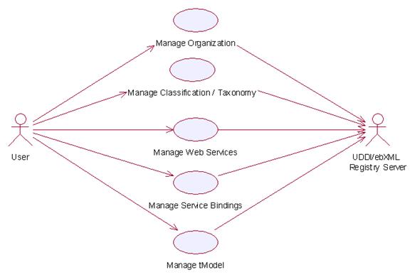
2.23.7Usage Scenario
2.23.7.1 Manage Classification / Taxonomy
2.23.7.1.1 Description
This use case allows any users to create, remove and view classification/taxonomy in the registry.
2.23.7.1.2 Flow of Events
2.23.7.1.2.1 Basic Flow
This use case starts when the users of registry server wishes to create, remove or view the classification/taxonomy in the registry server.
1: User initiates a request type to the Functional Element stating whether to create, remove or view classification/taxonomy.
2: The Functional Element checks whether the registry server exists.
3: The Functional Element checks the request. Based on the type of request, one of the sub-flows is executed.
If the request is to ‘Create Classification/Taxonomy’, then sub-flow 3.1 is executed.
If the request is to ‘View Classification/Taxonomy’, then sub-flow 3.2 is executed.
If the request is to ‘Remove Classification/Taxonomy’, then sub-flow 3.3 is executed.
3.1: Create Classification/Taxonomy.
3.1.1: Other Functional Element provides username, password and registry server URL to the Functional Element for authentication.
3.1.2: The Functional Element checks for the user validity in the identified registry server.
3.1.3: Other Functional Element provides classification/taxonomy information to be created in the registry server.
3.1.4: The Functional Element checks for the duplicate classification/taxonomy name.
3.1.5: The Functional Element creates the classification/taxonomy information in the private (default) or the public UDDI registry server according to the URL provided by other Functional Element, if it does not exist.
3.2: View Classification/Taxonomy.
3.2.1: The Functional Element retrieves all the classification/taxonomy from the identified registry server, which may be private (default) or public.
3.2.2: The Functional Element returns the classification/taxonomy information from the identified registry server to other Functional Element.
3.3: Remove Classification/Taxonomy.
3.3.1: Other Functional Element provides username, password and registry server URL to the Functional Element for authentication.
3.3.2: The Functional Element checks for the user validity in the identified registry server.
3.3.3: Other Functional Element provides classification/taxonomy key (i.e. UUID) to be removed from the identified registry server.
3.3.4: The Functional Element removes the classification/taxonomy information from the private (default) or the public UDDI registry server according to the URL provided by the user.
4: The Functional Element returns the status of the operation and the use case ends.
2.23.7.1.2.2 Alternative Flows
1: Registry Server Down.
1.1: In the basic flow 2, if the identified registry server is down, the Functional Element returns an error message and the use case ends.
2: Invalid Username And Password.
2.1: In the basic flow 3.1.2 and 3.3.2, if the username or password is invalid, the Functional Element returns an error message and the use case ends.
3: Classification/Taxonomy Key Not Found.
3.1: In the basic flow 3.3.3, if the classification/taxonomy key cannot be found in the specified registry server, the Functional Element returns an error message and the use case ends.
4: Duplicate Classification/Taxonomy.
4.1: In the basic flow 3.1.4, If the same classification/taxonomy name has been defined in the registry server, the Functional Element returns an error message and the use case ends.
2.23.7.1.3 Special Requirements
None
2.23.7.1.4 Pre-Conditions
In order to manage the classification/taxonomy in the registry server, users must be registered with the registry server. Username and password will be given when a user registers with a registry server.
2.23.7.1.5 Post-Conditions
None.
2.23.7.2 Manage Web Services
2.23.7.2.1 Description
This use case allows any users to register, remove and view Web Services in the private (default) as well as the public UDDI Registry Server.
2.23.7.2.2 Flow of Events
2.23.7.2.2.1 Basic Flow
This use case starts when the users of registry server wishes to create, remove and view Web Services.
1: User initiates a request type to the Functional Element stating whether to create, remove or view Web Services in the identified private or public registry server.
2: The Functional Element checks whether the registry server exists.
3: The Functional Element checks the request. Based on the type of request, one of the sub-flows is executed.
If the request is to ‘Create Web Service’, then sub-flow 3.1 is executed.
If the request is to ‘View Web Services’, then sub-flow 3.2 is executed.
If the request is to ‘Remove Web Service’, then sub-flow 3.3 is executed.
3.1: Create Web Service.
3.1.1: User provides username, password and registry server URL to the Functional Element for authentication.
3.1.2: The Functional Element checks for the user validity in the identified registry server.
3.1.3: Other Functional Element provides Web Service information to be created in the registry server.
3.1.4: The Functional Element creates the Web Service information in the private (default) or the public UDDI registry server according to the URL provided by other Functional Element.
3.2: View Web Services.
3.2.1: The Functional Element retrieves all the Web Services from the identified registry server for specific stated conditions like service name search, business name search, etc.
3.2.2: The Functional Element displays the Web Services information search results from the identified registry server to other Functional Element.
3.3: Remove Web Service
3.3.1 User provides username, password and registry server URL to the Functional Element for authentication.
3.3.2: The Functional Element checks for the user validity in the identified registry server.
3.3.3: Other Functional Element provides Web Service key (i.e. UUID) to be removed from the identified registry server.
3.3.4: The Functional Element removes the Web Service information from the private (default) or the public UDDI registry server according to the URL provided by other Functional Element.
4: The Functional Element returns the results of the operation and the use case ends.
2.23.7.2.2.2 Alternative Flows
1: Registry Server Down.
1.1: In the basic flow 2, if the identified registry server is down, the Functional Element returns an error message and the use case ends.
2: Invalid Username And Password.
2.1: In the basic flow 3.1.2 and 3.3.2, if the username or password is invalid, the Functional Element returns an error message and the use case ends.
3: Web Service Key Not Found.
3.1: In the basic flow 3.3.3, if the Web Service key cannot be found in the specified registry server, the Functional Element returns an error message and the use case ends.
2.23.7.2.3 Special Requirements
2.23.7.2.4 Pre-Conditions
In order to manage Web Services in the registry server, the users must be registered with the registry server. Username and password will be given when a user registers with a registry server.
2.23.7.2.5 Post-Conditions
None.
2.23.7.3 Manage Organization
2.23.7.3.1 Description
This use case allows any users to create, remove and view organization in the registry.
2.23.7.3.2 Flow of Events
2.23.7.3.2.1 Basic Flow
This use case starts when the users of registry server wishes to create, remove or view Organization.
1: User initiates a request type to the Functional Element stating whether to create, remove or view Organization.
2: The Functional Element checks whether the registry server exists.
3: The Functional Element checks the request. Based on the type of request, one of the sub-flows is executed.
If the request is to ‘Create Organization’, then sub-flow 3.1 is executed.
If the request is to ‘View Organizations’, then sub-flow 3.2 is executed.
If the request is to ‘Remove Organization’, then sub-flow 3.3 is executed.
3.1: Create Organization.
3.1.1: Other Functional Element provides username, password and registry server URL to the Functional Element for authentication.
3.1.2: The Functional Element checks for the user validity in the identified registry server.
3.1.3: Other Functional Element provides organization information to be created in the registry server.
3.1.4: The Functional Element checks for the duplicate organization name.
3.1.5: The Functional Element creates the organization information in the private (default) or the public UDDI registry server according to the URL provided by other Functional Element, if it does not exist.
3.2: View Organizations.
3.2.1: The Functional Element retrieves all the organizations from the identified registry server for specific stated conditions like organization name, key, etc.
3.2.2: The Functional Element returns the organization information from the identified registry server to other Functional Element.
3.3: Remove Organization.
3.3.1: Other Functional Element provides username, password and registry server URL to the Functional Element for authentication.
3.3.2: The Functional Element checks for the user validity in the identified registry server.
3.3.3: Other Functional Element provides Organization key (i.e. UUID) to be removed from the identified registry server.
3.3.4: The Functional Element removes the Organization information from the private (default) or the public UDDI registry server according to the URL provided by the user.
4: The Functional Element returns the status of the operation and the use case ends.
2.23.7.3.2.2 Alternative Flows
1: Registry Server Down.
1.1: In the basic flow 2, if the identified registry server is down, the Functional Element returns an error message and the use case ends.
2: Invalid Username And Password.
2.1: In the basic flow 3.1.2 and 3.3.2, if the username or password is invalid, the Functional Element returns an error message and the use case ends.
3: Organization Key Not Found.
3.1: In the basic flow 3.3.3, if the Organization key cannot be found in the specified registry server, the Functional Element returns an error message and the use case ends.
4: Duplicate Organization.
4.1: In the basic flow 3.1.4, If the same Organization name has been defined in the registry server the Functional Element returns an error message and the use case ends.
2.23.7.3.3 Special Requirements
None
2.23.7.3.4 Pre-Conditions
In order to manage Organization in the registry server, users must be registered with the registry server. Username and password will be given when a user registers with a registry server.
2.23.7.3.5 Post-Conditions
None.
2.23.7.4 Manage Service Binding
2.23.7.4.1 Description
This use case allows any users to register, remove and view Service Binding in the private (default) as well as the public UDDI Registry Server.
2.23.7.4.2 Flow of Events
2.23.7.4.2.1 Basic Flow
This use case starts when the users of registry server wishes to create, remove and view Service Binding.
1: User initiates a request type to the Functional Element stating whether to create, remove or view Service Binding in the identified private or public registry server.
2: The Functional Element checks whether the registry server exists.
3: The Functional Element checks the request. Based on the type of request, one of the sub-flows is executed.
If the request is to ‘Create Service Binding’, then sub-flow 3.1 is executed.
If the request is to ‘View Service Bindings’, then sub-flow 3.2 is executed.
If the request is to ‘Remove Service Binding’, then sub-flow 3.3 is executed.
3.1: Create Service Binding.
3.1.1: User provides username, password and registry server URL to the Functional Element for authentication.
3.1.2: The Functional Element checks for the user validity in the identified registry server.
3.1.3: Other Functional Element provides Service Binding information to be created in the registry server.
3.1.4: The Functional Element creates the Service Binding information in the private (default) or the public UDDI registry server according to the URL provided by other Functional Element.
3.2: View Service Bindings.
3.2.1: The Functional Element retrieves all the Service Bindings from the identified registry server for specific stated conditions like service binding key search, etc.
3.2.2: The Functional Element displays the Service Bindings information search results from the identified registry server to other Functional Element.
3.3: Remove Service Binding
3.3.1 User provides username, password and registry server URL to the Functional Element for authentication.
3.3.2: The Functional Element checks for the user validity in the identified registry server.
3.3.3: Other Functional Element provides Service Binding key (i.e. UUID) to be removed from the identified registry server.
3.3.4: The Functional Element removes the Service Binding information from the private (default) or the public UDDI registry server according to the URL provided by other Functional Element.
4: The Functional Element returns the results of the operation and the use case ends.
2.23.7.4.2.2 Alternative Flows
1: Registry Server Down.
1.1: In the basic flow 2, if the identified registry server is down, the Functional Element returns an error message and the use case ends.
2: Invalid Username And Password.
2.1: In the basic flow 3.1.2 and 3.3.2, if the username or password is invalid, the Functional Element returns an error message and the use case ends.
3: Service Binding Key Not Found.
3.1: In the basic flow 3.3.3, if the Service Binding key cannot be found in the specified registry server, the Functional Element returns an error message and the use case ends.
2.23.7.4.3 Special Requirements
2.23.7.4.4 Pre-Conditions
In order to manage Service Binding in the registry server, the users must be registered with the registry server. Username and password will be given when a user registers with a registry server.
2.23.7.4.5 Post-Conditions
None.
2.23.7.5 Manage tModel
2.23.7.5.1 Description
This use case allows any users to register, remove and view tModel in the private (default) as well as the public UDDI Registry Server.
2.23.7.5.2 Flow of Events
2.23.7.5.2.1 Basic Flow
This use case starts when the users of registry server wishes to create, remove and view tModel.
1: User initiates a request type to the Functional Element stating whether to create, remove or view tModel in the identified private or public registry server.
2: The Functional Element checks whether the registry server exists.
3: The Functional Element checks the request. Based on the type of request, one of the sub-flows is executed.
If the request is to ‘Create tModel’, then sub-flow 3.1 is executed.
If the request is to ‘View tModels’, then sub-flow 3.2 is executed.
If the request is to ‘Remove tModel’, then sub-flow 3.3 is executed.
3.1: Create tModel.
3.1.1: User provides username, password and registry server URL to the Functional Element for authentication.
3.1.2: The Functional Element checks for the user validity in the identified registry server.
3.1.3: Other Functional Element provides tModel information to be created in the registry server.
3.1.4: The Functional Element creates the tModel information in the private (default) or the public UDDI registry server according to the URL provided by other Functional Element.
3.2: View tModels.
3.2.1: The Functional Element retrieves all the tModels from the identified registry server for specific stated conditions like tModel name search, tModel key search, etc.
3.2.2: The Functional Element displays the tModel information search results from the identified registry server to other Functional Element.
3.3: Remove tModel.
3.3.1 User provides username, password and registry server URL to the Functional Element for authentication.
3.3.2: The Functional Element checks for the user validity in the identified registry server.
3.3.3: Other Functional Element provides tModel key (i.e. UUID) to be removed from the identified registry server.
3.3.4: The Functional Element removes the tModel information from the private (default) or the public UDDI registry server according to the URL provided by other Functional Element.
4: The Functional Element returns the results of the operation and the use case ends.
2.23.7.5.2.2 Alternative Flows
1: Registry Server Down.
1.1: In the basic flow 2, if the identified registry server is down, the Functional Element returns an error message and the use case ends.
2: Invalid Username And Password.
2.1: In the basic flow 3.1.2 and 3.3.2, if the username or password is invalid, the Functional Element returns an error message and the use case ends.
3: tModel Key Not Found.
3.1: In the basic flow 3.3.3, if the tModel key cannot be found in the specified registry server, the Functional Element returns an error message and the use case ends.
2.23.7.5.3 Special Requirements
2.23.7.5.4 Pre-Conditions
In order to manage tModel in the registry server, the users must be registered with the registry server. Username and password will be given when a user registers with a registry server.
2.23.7.5.5 Post-Conditions
None.
2.24 Service Router Functional Element (new)
2.24.1 Motivation
Enable
capability for easy and simple mechanisms for invoking web services by:
·
Providing a façade to service requesters for services
location transparency, services reliability.
· Performing pre- and post- processing before and after web services invocation.
This Functional Element fulfills the
following requirements from the Functional Elements Requirements:
Primary Requirements
1.3 PROCESS-250 to PROCESS-260.
Secondary Requirements
1.4 None
2.24.2 Terms Used
|
Terms |
Description |
|
Façade |
Façade is exterior face or interface of a
system, which hides the implementation details of the system. |
|
Functional handler |
Functional handler is a software component that performs certain business processing on the parameters passed. |
Figure 30 depicts the basic
concepts of how the participating entities collaborate together in the Service
Router Functional Element. All the invocations from service client come to the
Service router which servers as façade. The Service Router routes the
invocation the actual web services. Functional handlers could be incorporated
in the Functional Element or other Functional Elements. The functional handlers
can be invoked before or after the actual web services are invoked.
|
|
|||
|
Figure 30: An Overview of the Service Router Functional Element |
2.24.3 Key Features
Implementations of the Service Router
Functional Element are expected to provide the following key features:
1. The Functional Element MUST provide mechanism as façade for web services invocations. This mechanism has the following capabilities:
1.1. Provide a single access point for web service invocation.
1.2. Provide the location transparency of actual web services.
2. The Functional Element MUST provide capability to route web services invocation on behalf of service requesters to the specified actual web services.
3. The Functional Element MUST provide capability to manage web services invocation in the aspects of invocation time-out, transaction management.
4. The Functional Element MUST provide capability to manage the registration of web services that are going to be invoked.
5. The Functional Element MUST provide capability to deploy registered web services automatically into the façade.
6. The Functional Element MUST provide mechanism to incorporate functional handlers.
7. The Functional Element MUST provide capability to perform processing by invoking functional handlers defined for a web services invocation before the web services is really invoked.
8. The Functional Element MUST provide capability to perform processing by invoking functional handlers for a web services invocation after the web services is invoked.
9. The Functional Element MUST provide capability to manage functional handlers.
10. The Functional Element MUST provide capability to manage the parameter mappings between two adjacent functional handlers and parameter mapping between functional handler and web services.
In addition, the following key features could be provided to enhance the Functional Element further:
The Functional Element MAY provide capability to invoke the alternative web services if the actual web services that is targeted to invoke is not available.
2. The Functional Element MAY provide the capability to define a sequence of functional handlers for a web services for a web services invocation.
3. The Functional Element MAY provide capability to enable the invocation of functional handlers in pre-defined sequence for a web for a web services invocation.
2.24.4 Interdependencies
None.
2.24.5 Related Technologies and Standards
None.
2.24.6Model
|
|
|
Figure 31: Model Of the Service Router
Functional Element [[27]] |

2.24.7 Usage Scenarios
2.24.7.1 Manage Service Registration
2.24.7.1.1 Description
This use case allows the
user to register, remove and view web services from or to the service router.
· Register Web Service
Web services details are registered to the service router.
· Delete Web Service
Web services are removed from the service router.
· View Web Service
View the registration information of a web
service.
2.24.7.1.2 Flow of Events
2.24.7.1.2.1 Basic Flow
This use case starts when
the user of service router wishes to register, remove and view web services
registration.
1: The user initiates a request type to the Functional Element stating whether to register, remove or view web services registration in the service router.
2: The Functional Element checks the request. Based on the type of request, one of the sub-flows is executed. If the request is to register a new web service in the service router, system executes ‘Register Web Service’. If the request is to view web services from the service router, system executes ‘View Web Services’. If the request is to remove a web service from the service router, system executes ‘Remove Web Service’.
2.1: Register Web Service.
2.1.1: The user provides the
2.1.2: The user provides other web service information to be kept in the service router.
2.1.3:
The Functional Element retrieves web service information from the
2.2: View Web Services.
2.2.1: The Functional Element retrieves the service from the registry with the specific service name.
2.2.2: The Functional Element returns the web services information results to the user.
2.3: Remove Web Service
2.3.1: The user provides web service name to be removed from the identified registry server.
2.3.2: The Functional Element removes the web service information from the registry.
3: The Functional Element responses the status of the operation whether it is successful or failure to the user and the use case ends.
2.24.7.1.2.2 Alternative Flows
1:
1.1:
In the Basic Flow 2.1.1, if the
2: Service does not exist
2.1: In the Basic Flow 2.2.1 and 2.3.1, if the service name does not exist, “Service does not exist” error will be sent back.
2.24.7.1.3 Special Requirements
None.
2.24.7.1.4 Pre-Conditions
None.
2.24.7.1.5 Post-Conditions
None.
2.24.7.2 Manage Handler
2.24.7.2.1 Description
This use case allows any user to add, remove
and view handler to the service router.
2.24.7.2.2 Flow of Events
2.24.7.2.2.1 Basic Flow
This use case starts when the user of registry server wishes to add,
remove or view web service handlers.
1: The user initiates a request type to the Functional Element stating
whether to add, remove or view web service handlers.
2: The Functional Element checks the request. Based on the type of request, one of the
sub-flows is executed. If the request is
to add a new web service handler to the router, system executes ‘Add Service
Handler’. If the request is to view web
service handlers, system executes ‘View Service Handlers’. If the request is to remove a handler from
the router, system executes ‘Remove Service Handler’.
2.1: Add Service Handler.
2.1.1: The user
provides handler name and location to The Functional Element.
2.1.2: The
service adds the information to the registry.
2.2: View Service Handlers.
2.2.1: The
Functional Element receives a handler name from the user.
2.2.2: The
Functional Element returns the information of the handler to the user.
2.3: Remove Service Handler.
2.3.1: The user
provides handler name to be removed from the service router.
2.3.2: The
Functional Element removes the service handler from the registry.
3: The Functional Element responses the status of the operation whether
it is successful or failure to the user and the use case ends.
2.24.7.2.2.2 Alternative Flows
1: Handler name error.
1.1: In the Basic Flow 2.2.1 and 2.3.1, if
the handler name does not exist, system displays an error message and exits the
use case.
2.24.7.2.3 Special Requirements
None.
2.24.7.2.4 Pre-Conditions
None.
2.24.7.2.5 Post-Conditions
None.
2.24.7.3 Manage Service’s Handler
2.24.7.3.1 Description
This use case allows the user to add, remove and view handlers to the
services registered in the service router.
·
Add a
handler to a service
New handler is
added to a registered service.
·
Remove
a handler to a service
Existing handler
is removed from a registered service.
·
View
service’s handler
Existing handlers of a service could be viewed by the user.
2.24.7.3.2 Flow of Events
2.24.7.3.2.1 Basic Flow
This use case starts when the user of service router wishes to add,
remove or view handlers to a service.
1: The user initiates a request type to the Functional Element stating
whether to add, remove or view handlers to a service.
2: The Functional Element checks the request. Based on the type of request, one of the
sub-flows is executed. If the request is
to add a new web service handler to a registered web service, system executes
‘Add Service Handler’. If the request is
to view web service handlers, system executes ‘View Service Handlers’. If the request is to remove a handler from a
service, system executes ‘Remove Service Handler’.
2.1: Add Service Handler.
2.1.1: The user provides handler name,
service name and parameter mappings to The Functional Element.
2.1.2: The service adds the information
to the registry.
2.2: View Service Handlers.
2.2.1: The
Functional Element receives the service name from the user.
2.2.2: The
Functional Element retrieves all the handlers and return to the user.
2.3: Remove Service Handler.
2.3.1: The user provides handler name and
service name to be removed from the service router.
2.3.2: The
Functional Element removes the service handler from the registry.
3: The Functional Element responses the status of the operation whether
it is successful or failure to the user and the use case ends.
2.24.7.3.2.2 Alternative Flows
1: Handler name or service name does not exist.
1.1: In the Basic Flow 2.1.1, 2.2.1 and
2.3.1, if the service name or the handler name does not exist, system displays
an error message and exits the use case.
2.24.7.3.3 Special Requirements
None.
2.24.7.3.4 Pre-Conditions
None.
2.24.7.3.5 Post-Conditions
None.
2.24.7.4 Deploy Service
2.24.7.4.1 Description
This use case allows the user to deploy registered services to an
application server.
·
Add
server information to The Functional Element
New server is
added to a registered service.
·
Remove
server information to The Functional Element
Existing server
is removed from a registered service.
·
View
server information
Existing server
information could be viewed by the user.
·
Deploy
service
Deploy a
registered service to a server.
.
2.24.7.4.2 Flow of Events
2.24.7.4.2.1 Basic Flow
This use case starts when the user of service router wishes to add,
remove, view server information or deploy a web service to a server.
1: The user initiates a request type to the Functional Element stating
whether to add, remove or view server’s information or deploy service.
2: The Functional Element checks the request. Based on the type of request, one of the
sub-flows is executed. If the request is
to add a server to the router, system executes ‘Add Server’. If the request is to view server information,
system executes ‘View Server’. If the
request is to remove a server from the router, system executes ‘Remove
Server’. If the request is to deploy a
service to a server, system executes ‘Deploy Service’.
2.1: Add Server.
2.1.1: The user
provides server name and location of the server.
2.1.2: The
service adds the information to the registry.
2.2: View Server.
2.2.1: The
Functional Element receives the server name from the user.
2.2.2: The
Functional Element retrieves the information and return to the user.
2.3: Remove Server.
2.3.1: The user
provides the server name from the service router.
2.3.2: The
Functional Element removes the server from the registry.
2.4: Deploy Service.
2.4.1: The user
provides the server name and service name from the service router.
2.4.2: The Functional Element generate code
package the service and deploy it to the server.
3: The Functional Element responses the status of the operation whether
it is successful or failure to the user and the use case ends.
2.24.7.4.2.2 Alternative Flows
1: Service name or server name does not exist.
1.1: In the Basic Flow 2.2.1, 2.3.1 and
2.4.1, if the service name or the server name does not exist, system displays
an error message and exits the use case.
2.24.7.4.3 Special Requirements
None.
2.24.7.4.4 Pre-Conditions
None.
2.24.7.4.5 Post-Conditions
None.
2.24.7.5 Invoke Service
2.24.7.5.1 Description
This use case allows the user to invoke registered services through the
Service Router. It is expected to utilise the Notification FE and Log Util FE
in the implementation of this use case.
2.24.7.5.2 Flow of Events
2.24.7.5.2.1 Basic Flow
This use case starts when the user of service router wishes to invoke a
deployed or registered service.
1: The user initiates a request to the Service Router.
2: The Functional Element checks the request, and determines if the
invoked service has any pre-invocation Functional Handlers. If so, the handlers
are invoked.
3: The Functional Element then routes the request to the actual service
based on registration information captured.
4: When the result from the actual service is returned, the Functional
Element checks if there is any post-invocation Functional Handlers. If so, the
handlers are invoked.
5: The Functional Element returns the result of invocation to the user
and the use case ends.
2.24.7.5.2.2 Alternative Flows
1: Functional Handlers are not available.
1.1: In the Basic Flow 2 and 4, if the Functional
Handlers are not available, an error message will be returned, and the use case
ends.
2: Invoked Service is not available.
2.1: In the Basic Flow 3, if the invoked
Service is not available, an error message will be returned, and the use case
ends.
2.24.7.5.3 Special Requirements
None.
2.24.7.5.4 Pre-Conditions
None.
2.24.7.5.5 Post-Conditions
None.
2.25 Service Tester Functional Element (Deprecated)
This Functional
Element has been deprecated in this version. Please refer to its replacement, 2.15 QoS Functional Element (new) for further details.
2.26 Transformer Functional Element (new)
2.26.1 Motivation
Different
applications support different format of files or message. Sometimes same information needs to be
represented in different format in different use cases. This element tries to provide a framework to
facilitate transformation between files or messages.
This Functional Element fulfills the
following requirements from the Functional Elements Requirements:
·
Primary
Requirements
·
DELIVERY-150,
·
DELIVERY-151,
·
DELIVERY-152,
·
DELIVERY-153,
·
DELIVERY-155, and
·
DELIVERY-157.
2.26.2
Terms Used
|
Terms |
Description |
|
API Handlers |
Binary components which are deployed at the same
location as the element. This component provides a set of APIs for the
element to invoke to transform files or messages. |
|
Web Services
Handler |
A web service
which are used by the element to invoke to transform files or messages. |
|
|
Web Services
Description Language |
|
XSLT |
Extensible
Stylesheet Language Transformation |
Figure 32 depicts
the basic concepts of 2 steps approach of Transformer
Functional Element. Step 1 begins when the user (service requester) requests to define
supported message, file types, XSLT templates and process handlers. The Function Element persists these
definitions the return the results. Step 2 begins when the user requests for file or message transformation. The user provides messages or files to be
transformed. The Functional Element will do the transformation
and returns the result to the user.
|
|
|
Figure 32: An Overview of Transformer Functional Element |
2.26.3 Key Features
Implementations of the Transformer
Functional Element are expected to provide the following key features:
1. The Functional Element MUST provide the capability to manage supported files and messages.
2.
The
Functional Element MUST provide the capability to manage XSLT templates.
3.
The
Functional Element MUST provide the capability to manage handlers for transformation.
4.
The
Functional Element MUST provide the handler to transform SOAP,
In addition, the following key features could be provided to enhance the Functional Element further:
1. The Functional Element MAY provide the capability to chain handlers.
2. The Functional Element MAY provide the capability to measure the performance of handlers.
3.
The
Functional Element MAY provide the capability to select the efficient handlers to do the
transformation.
2.26.4
Interdependencies
|
Direct Dependency |
|
|
Log Utility
Functional Element |
The Log Utility Functional Element is used to record the data. |
2.26.5 Related Technologies and Standards
|
Specifications |
Description |
|
SOAP 1.2 |
The ability to parse the SOAP message. |
|
|
The ability to parse the |
2.26.6 Model
|
|
|
Figure
33: Model Of the
Transformer Functional Element |

2.26.7Usage Scenarios
2.26.7.1 Manage Formats
2.26.7.1.1 Description
This
use case allows the user to manage file or message formats supported by this element.
2.26.7.1.2 Flow of Events
2.26.7.1.2.1 Basic Flow
This use case starts when the user
wants to manage file or
message formats.
1: The user
provides the management operation to the functional element.
2: Based on the operation one of the following sub-flow is
executed. If the operation is “add-
format” sub-flow 2.1 is executed. If the
operation is “delete-format” sub-flow 2.2 is executed. If the operation is “query-format” sub-flow
2.3 is executed.
2.1: Add format
2.1.1: The system gets the format name, file
extension name.
2.1.2: The system save this information.
2.2: Delete
format
2.2.1: The system
gets the format name.
2.2.2: The system
deletes format information.
2.3: Query
format:
2.3.1: The system
gets the format name.
3: The Functional Element responses the status of the operation whether it is successful or failure to the user and the use case ends.
2.26.7.1.2.2 Alternative Flows
1: Format Name Already Registered.
1.1
In Basic Flow 2.1.2, if the format name already registered, the system will
assign error message to the result message.
2: Format Name Does Not Exist
2.1
In Basic Flow 2.2.2, if the format name does not exist, the system will assign
error message to the result message.
2.26.7.1.3 Special Requirements
None.
2.26.7.1.4
Pre-Conditions
None.
2.26.7.1.5 Post-Conditions
None.
2.26.7.2 Manage Methods
2.26.7.2.1 Description
This use case allows the user to manage the methods that are used to do the
transformation.
2.26.7.2.2 Flow of Events
2.26.7.2.2.1 Basic Flow
This use case starts when a user wants to manage the methods that are used to do the transformation.
1. The user provides the management operation
and data.
2. Based on the operation it specified, one
of the following sub-flows is expected. If
the operation is ‘Add Method’, then sub-flow 2.1 is executed. If the operation is ‘Delete Method’, then
sub-flow 2.2 is executed. If the
operation is “Query Method”, then sub-flow 2.3 is executed.
2.1: Add Method.
2.1.1: The
user sets the file method name, type (API or Web Service), Input file format
location and Output file format location, or user submits the WDSL of a known web service.
2.1.2: The system save this information.
2.2: Delete
Method.
2.2.1: The user
sets the method name.
2.2.2: The system deletes this information
2.3: Query Method.
2.3.1: The user sets the method name, or input format, or output
format.
3: The Functional Element responses the status of the operation whether it is successful or failure to the user and the use case ends.
2.26.7.2.2.2 Alternative Flows
1: Method Name Already Registered.
1.1
In Basic Flow 2.1.2, if the format name already registered, the system will
assign error message to the result message.
2: Method Name Does Not Exist.
2.1
In Basic Flow 2.2.2, if the format name does not exist, the system will assign
error message to the result message.
2.26.7.2.3 Special Requirements
None.
2.26.7.2.4
Pre-Conditions
None.
2.26.7.2.5 Post-Conditions
None.
2.26.7.3 Perform Transformation
2.26.7.3.1 Description
This use case allows the user to transform a file from one format to another format.
2.26.7.3.2 Flow of Events
2.26.7.3.2.1 Basic Flow
This use case starts when a user wants to transform a file from one format to another format.
1: The user set the
file name to be transformed and the destination format.
2: The system checks all the methods which
use this file as input.
3: The system checks all the methods which
use the destination format as output.
4: Select one method based on the performance
data recorded before.
5: Invoke the methods and save the performance data.
6: Return the results and the use case ends.
2.26.7.3.2.2
Alternative Flows
1: If in Basic Flow 4 there is there is no method to do the
transformation, the system return error message to the user and this use case
ends.
2.26.7.3.3 Special Requirements
None.
2.26.7.3.4
Pre-Conditions
None.
2.26.7.3.5 Post-Conditions
None.
2.26.7.4 Define Chain Handler
2.26.7.4.1 Description
This use case allows the user to create new
handler based on the existing handler if a transformation could be done
directly but could be done indirectly through a chain of existing handler.
2.26.7.4.2 Flow of Events
2.26.7.4.2.1 Basic Flow
1: User sets the
chain handler name and the handlers involved in this chain.
2: The system gets the input format name of
the first handler and the output format name of the last handler.
3: The system save this information.
4: Return the results to the user and end the
use case.
2.26.7.4.2.2
Alternative Flows
1: If the handler name could not be found in
Basic Flow 2, system returns the results to the user and the use case ends.
2.26.7.4.3 Special Requirements
None.
2.26.7.4.4
Pre-Conditions
None.
2.26.7.4.5 Post-Conditions
None.
2.26.7.5 Choose Handler
2.26.7.5.1 Description
This
use case allows the system to choose a handler for transformation.
2.26.7.5.2 Flow of Events
2.26.7.5.2.1 Basic Flow
This use case starts when the transform use case needs a handler to do the transformation.
1. The system checks the handlers that match
the input and out put format.
2: The system
returns the name of the handler to the transform use case and ends this use
case.
2.26.7.5.2.2 Alternate Flow
1: In Basic Flow 1, if there are more
handlers available and performance data are available, then the system select
the handler with the best performance data.
Otherwise select any one.
2: In Basic Flow 1, if the handler is a XSLT
template, return the template name to the transform.
2.26.7.5.3 Special Requirements
None.
2.26.7.5.4
Pre-Conditions
None.
2.26.7.5.5 Post-Conditions
None.
2.26.7.6 Save Performance Data
2.26.7.6.1 Description
This use case saves performance data of each
handler.
2.26.7.6.2 Flow of Events
2.26.7.6.2.1 Basic Flow
This use case starts when user
wants to measure the
performance of the handlers.
1: It starts time counting.
2: Collection CPU information, DISK access
information and Network traffic information.
3: Waiting for the termination of the handler.
4: Save this information and end the use
case.
2.26.7.6.2.2
Alternative Flows
1: In Basic Flow 3, If the log file is not
available, the Functional Element returns an error and the user case ends.
2.26.7.6.3 Special Requirements
None.
2.26.7.6.4 Pre-Conditions
None.
2.26.7.6.5 Post-Conditions
None.
2.27 User Management Functional Element
2.27.1Motivation
Basic user accounts management facilities,
Ability to extend dynamically from the basic set of account information,
Capability for configurable policies governing account management,
Providing log trails for user activities, and
Management of user authentication means, either directly or indirectly.
This Functional Element fulfills the following requirements from the Functional Elements Requirements, Working Draft 01a:
Primary Requirements
·
MANAGEMENT-001 to MANAGEMENT-003,
·
MANAGEMENT-005,
·
MANAGEMENT-008,
·
MANAGEMENT-012, and
·
SECURITY-002 (all).
Secondary
Requirements
·
SECURITY-001.
2.27.2Terms Used
|
Terms |
Description |
|
Namespace |
Namespace is use to segregate the instantiation of the application across different application domains. If a company has two separate standalone application, for example, an email application and an equipment booking application, then these two are considered as separate application domains. |
|
User |
A user is loosely defined to include both human and virtual users. Virtual users could include service users and application (or machine) users that are utilising other services in a SOA environment. |
|
User Access Management / UAM |
User Access Management or UAM refer to the concept of managing users in a holistic manner, considering all aspect which includes: Defining a set of basic user information that should be stored in any enterprise application. Providing a means to extend this basic set of user information when needed. Simplifying management by grouping related users together through certain criteria. Having the flexibility of adopting both coarse/fine grain access controls. |
|
User Repository |
User Repository is where the user information is stored. It can be a database or a flat file. |
2.27.3Key Features
Implementations of the User Management Functional Element are expected to provide the following key features:
1. The Functional Element MUST provide a User Repository.
2. The Functional Element MUST be able to control access to such a User Repository.
3. The Functional Element MUST provide a basic User structure with a set of pre-defined attributes.
4. The Functional Element MUST provide the capability to extend on the basic User structure dynamically.
5. As part of Key Feature (4), this dynamic extension MUST be definable and configurable at runtime implementation of the Functional Element.
6. The Functional Element MUST provide the capability to manage the creation and deletion of instances of Users based on defined structure.
7. The Functional Element MUST provide the capability to manage all the information (attribute values) stored in such Users. This includes the capability to:
7.1. Retrieve and update attribute’s values belonging to a User,
7.2. Generate a random password,
7.3. Encrypt sensitive user information, and
7.4. Authenticate a user.
8. As part of Key Feature (7.4), the authentication of a User MUST be achieved at least through the use of a password.
9. The Functional Element MUST provide a mechanism for managing Users across different application domains.
Example:
Namespace control mechanism
In addition, the following key features could be provided to enhance the Functional Element further:
1. The Functional Element MAY provide a mechanism to control the username format.
Example: Usernames must be at least 8 characters long.
2. The Functional Element MAY provide additional security mechanisms to enhance the security of sensitive information like user passwords.
Example: Passwords are stored in security tokens, or a
more secure encryption algorithms for passwords.
3. If Key Feature (2) is provided, the Functional Element MAY also provide a selection of selectable encryption algorithms.
4. The Functional Element MAY provide additional security policies to ensure that systems are not compromised.
Example: Passwords must be changed every 30 days.
5. If Key Feature (4) is provided, the Functional Element MAY also provide a facility to notify users before the password expires.
2.27.4Interdependencies
|
|
|
|
Group Management Functional Element |
The Group Management Functional Element may be used to provide useful aggregation of the users. |
|
Phase and Lifecycle Management Functional Element |
The Phase and Lifecycle Management Functional Element may be used to maintain the relationships between various phases of a project lifecycle and the group who is working on it. |
|
Role and Access Management Functional Element |
The Role and Access Management Functional Element may be used to manage the user’s access rights by virtue of it’s association with a group, phase or even the complete lifecycle of the project. |
2.27.5Related Technologies and Standards
None
2.27.6Model
|
|
|
Figure 34: Model Of the User Management Functional Element [[28]] |
2.27.7Usage Scenarios
2.27.7.1 Manage Naming Policy
2.27.7.1.1 Description
This use case allows any user to manage naming policy when creating/updating user accounts. The service user may create, update, retrieve and delete a naming policy.
2.27.7.1.2 Flow of Events
2.27.7.1.2.1 Basic Flow
This use case starts when any user wants to manage naming policy for creating/updating user account.
1: The user sends Manage Naming Policy request to the Functional Element together with the specified operation.
2: Functional Element gets the operation. Based on the operation, one of the sub-flows is executed.
If the service user provides ‘Create Naming Policy’, then sub-flow 2.1 is executed.
If the service user provides ‘Update Naming Policy’, then sub-flow 2.2 is executed.
If the service user provides ‘Delete Naming Policy’, then sub-flow 2.3 is executed.
2.1: Create Naming Policy.
2.1.1: The service user specifies namespace, name and description of the policy to create, for example, the policy name may be name length, the policy description may be “=7”.
2.1.2: The Functional Element checks the existing naming policy.
2.1.3: The Functional Element generates naming policy information and adds to the Functional Element and the use case ends.
2.2: Update Naming Policy.
2.2.1: The service user specifies the policy to update.
2.2.2: The Functional Element retrieves the existing naming policy information.
2.2.3: The service user provides the update naming policy information according to the policy name used in creating a naming policy.
2.2.4: The Functional Element updates the naming policy with the updated information and ends use case.
2.3: Retrieve Naming Policy.
2.3.1: The service user specifies the policy to retrieve.
2.3.2: The Functional Element retrieves the existing naming policy information and ends the use case.
2.4: Delete Naming Policy.
2.4.1: The service user specifies the policy to delete.
2.4.2: The Functional Element retrieves the existing naming policy information.
2.4.3: The Functional Element deletes the naming policy from the Functional Element and the use case ends.
2.27.7.1.2.2 Alternative Flows
1: Invalid Policy.
1.1: If in the basic flow 2.1.1, Functional Element detects any invalid description, Functional Element returns general error message and ends the use case.
2: Naming Policy already exists.
2.1: If in the basic flow 2.1.2, the Functional Element checks the existing naming policy and finds the naming policy already exists. The Functional Element returns an error and ends the use case.
2.27.7.1.3 Special Requirements
2.27.7.1.4 Pre-Conditions
None.
2.27.7.1.5 Post-Conditions
If the use case was successful, the naming policy information is added to the Functional Element. To do any creating and updating of User information after the naming policy is added must satisfy the naming policies defined. If unsuccessful, the Functional Element’s state is unchanged.
2.27.7.2 Manage User Definition
2.27.7.2.1 Description
The use case allows any user to manage user definition when more basic user definition can not satisfied in creating/updating user accounts. The service user may create, update, retrieve and delete a user definition.
2.27.7.2.2 Flow of Events
2.27.7.2.2.1 Basic Flow
This use case starts when any user wants to manage user definition for creating/updating user account.
1: The user sends Manage User Definition request to the Functional Element together with the specified operation.
2: Functional Element gets the operation. Based on the operation, one of the sub-flows is executed.
If the service user provides ‘Create User Definition’, then sub-flow 2.1 is executed.
If the service user provides ‘Update User Definition’, then sub-flow 2.2 is executed.
If the service user provides ‘Delete User Definition’, then sub-flow 2.3 is executed.
2.1: Create User Definition.
2.1.1: The service user specifies namespace, name and description of the user definition fields to create.
2.1.2: The Functional Element checks the existing user definition fields (including basic ones).
2.1.3: The Functional Element generates user definition information and adds to the Functional Element and the use case ends.
2.2: Update User Definition.
2.2.1: The service user specifies the user definition field to update.
2.2.2: The Functional Element retrieves the existing user definition information.
2.2.3: The service user provides the update user definition information.
2.2.4: The Functional Element updates the user definition with the updated information and ends use case.
2.3: Retrieve User Definition.
2.3.1: The service user specifies the user definition to retrieve.
2.3.2: The Functional Element retrieves the existing user definition information and ends the use case.
2.4: Delete User Definition.
2.4.1: The service user specifies the user definition to delete.
2.4.2: The Functional Element retrieves the existing user definition information.
2.4.3: The Functional Element deletes the user definition from the Functional Element and the use case ends.
2.27.7.2.3 Alternative Flows
1: Invalid User Definition.
1.1: If in basic flow 2.1.1, Functional Element detects any invalid description, Functional Element returns general error message and ends the use case.
2: User Definition already exists.
2.1: If in basic flow 2.1.2, the Functional Element checks the existing user definition and finds the user definition already exists. The Functional Element returns an error and ends the use case.
3: User Definition not exists.
3.1: If in basic flow 2.2.2, 2.3.2 and 2.4.2, the Functional Element checks the existing user definition and finds the user definition does not exist. The Functional Element returns an error and ends the use case.
2.27.7.2.4 Special Requirements
None
2.27.7.2.5 Pre-Conditions
None.
2.27.7.2.6 Post-Conditions
If the use case was successful, the user definition information is added to the Functional Element. Thereafter, when creating and updating User, the User information must satisfy the user definition defined earlier. If the use case fails, the Functional Element’s state is unchanged.
2.27.7.3 Manage User
This use case describes the management of a user, namely the creation, deletion, retrieval and update of the user.
2.27.7.3.1 Flow of Events
2.27.7.3.1.1 Basic Flow
This use case starts when the user wants to manage a user.
If user wants to ‘Create User, then basic flow 1 is executed.
If user wants to ‘Retrieve User, then basic flow 2 is executed.
If user wants to ‘Update User, then basic flow 3 is executed.
If user wants to ‘Delete User, then basic flow 4 is executed.
1: Create User.
1.1: User provides the information that is necessary for creating a user.
1.2: The Functional Element validates the user information provided against the naming policy.
1.3: The Functional Element validates the user information provided against the user’s definition.
1.4: Functional Element creates the user and the use case ends.
2: Retrieve User.
2.1: User provides the necessary information for retrieving the complete user’s attributes.
2.2: The Functional Element returns the user’s information and the use case ends.
3: Update User.
3.1: User provides the necessary information for updating the group’s attributes.
3.2: The Functional Element validates the user’s information provided against the naming policy.
3.3: The Functional Element validates the user information provided against the user’s definition.
3.4: The Functional Element updates the user and the use case ends.
4: Delete User.
4.1: User provides the necessary information for deleting a user group.
4.2: Functional Element deletes the user and the use case ends.
2.27.7.3.1.2 Alternative Flows
1: User Exist.
1.1: In basic flow 1.4, if the Functional Element detects an identical user, the Functional Element returns an error message and the use case ends.
2: User Does Not Exist.
1.1: In basic flow 2.2, 3.4 and 4.2, if the Functional Element cannot find a user that matches the user’s criteria, the Functional Element returns an error message and the use case ends.
2.27.7.3.2 Special Requirements
None.
2.27.7.3.3 Pre-Conditions
None.
2.27.7.3.4 Post-Conditions
None.
2.27.7.4 Authenticate User
2.27.7.4.1 Description
This use case allows users to authenticate a user.
2.27.7.4.2 Flow of Events
2.27.7.4.2.1 Basic Flow
This use case starts when users wish to authenticate a user.
1: Users provide user name and password to Functional Element.
2: The Functional Element checks the user name and password.
3: The Functional Element returns the result to users and the use case ends.
2.27.7.4.2.2 Alternative Flows
None.
2.27.7.4.3 Special Requirements
None.
2.27.7.4.4 Pre-Conditions
None.
2.27.7.4.5 Post-Conditions
None.
2.27.7.5 Manage Password
This use case describes the management of password in this Functional Element.
2.27.7.5.1 Flow of Events
2.27.7.5.1.1 Basic Flow
This use case starts when the user wants to obtain an encrypted password. This can be achieved via one of the following basic flow.
If user wants to ‘Generate Password’, then basic flow 1 is executed.
If user wants to ‘Encrypt Password’, then basic flow 2 is executed.
1: Generate Password
1.1: The user specifies the option of format of password among available options in the Functional Element.
1.2: The Functional Element generates clear text password based on the format specified by the service user.
1.3: The Functional Element includes “Encrypt Password’ use case to encrypt the clear text password.
1.4: The Functional Element returns the clear text password and encrypted password to user and the use case ends.
2: Encrypt Password
1.1: The user provides clear text password to Functional Element.
1.2: The user specifies the encryption algorithm to be used.
1.3: The Functional Element encrypts the clear text password.
1.4: The Functional Element returns the encrypted password to user and the use case ends.
2.27.7.5.1.2 Alternative Flows
None.
2.27.7.5.2 Special Requirements
None.
2.27.7.5.3 Pre-Conditions
None.
2.27.7.5.4 Post-Conditions
None.
2.28 Web Service Aggregator Functional Element
2.28.1Motivation
In any Web Service-enabled application, it is expected that complex business functions have to be realized via aggregation of multiple Web Services. This Functional Element is expected to fulfill the needs arising out of Web Services composition. As such it will cover aspects that include:
Facilitating the composition of Web Services, and
Testing of aggregated Web Services.
This Functional Element fulfills the following requirements from the Functional Elements Requirements, Working Draft 01a:
Primary Requirements
·
PROCESS-010 to PROCESS-014.
Secondary
Requirements
·
PROCESS-131
2.28.2Terms Used
|
Terms |
Description |
|
Aggregated Web Service |
Aggregated Web Service is single Web Services that invoke multiple Web Services to realize its functionality. |
|
Composition Rule |
A Composition Rule is an expression specifying how individual Web Services are invoked to form aggregated Web Services. It includes the name of Web Services that are included in aggregation, specification of aggregation sequence, data dependency among the individual Web Services. |
The following diagram shows the meaning of the terms in the context of Web Services aggregation.
|
|
|
Figure 35: An Overview of the Web Service Aggregator Functional Element |
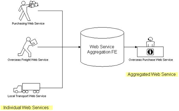
2.28.3Key Features
1. The Functional Element MUST provide a mechanism for composing any number of Web Services into single Web Service according to specified Composition Rule(s).
2. Individual web services can reside at any location, but it is expected to be accessible.
3. As
part of Key Feature (1), the
4. The Functional Element MUST support the definition, modification and removal of Composition Rules.
5. The Functional Element MUST encapsulate the composition logic used into an interpretable XML-based script based on a particular standard*.
Example: BPEL
or
In addition, the following key features could be provided to enhance the Functional Element further:
1. The Functional Element MAY provide the capability to transform the interpretable XML-based script into an executable program.
2. If Key Feature (1) is provided, then the Functional Element MAY also have the following capabilities:
2.1 The ability to test the functionality of the aggregated Web Service,
2.2
A
2.3 The capability to publish the aggregated Web Service into an UDDI-compliant registry
2.28.4Interdependencies
|
Interaction Dependencies |
|
|
Services Tester Functional Element |
The Services Tester Functional Element may be used to test the performance of the aggregated web services |
|
Service Registry Functional Element |
The Services Registry Functional Element may be used to publish the aggregated web services |
2.28.5Related Technologies and Standards
|
Specific References |
|
|
Business
Process Execution Language for Web Services version 2.0 [[29]] |
Web
Services Business Process Execution Language Version 2.0, Committee Draft, |
2.28.6Model
|
|
|
Figure 36: Model Of the Web Service Aggregation Functional Element [[30]] |
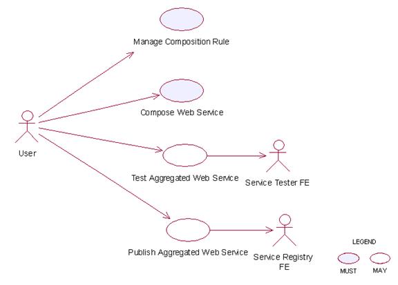
2.28.7Usage Scenarios
2.28.7.1 Manage composition rule
2.28.7.1.1 Description
This use case allows the user to manage the
composition rule used for Web Services aggregation.
2.28.7.1.2 Flow of Events
2.28.7.1.2.1 Basic Flow
The use case begins when the user wants to manage a composition rule.
1: The user sends a request to the Functional Element together with the composition rule and operation.
2: Based on the operation it specified, one of the following sub-flows is executed:
If the operation is ‘Define a rule’, then sub-flow 2.1 is executed.
If the operation is ‘Update a rule’, then sub-flow 2.2 is executed.
If the operation is ‘Retrieve a rule’, then sub-flow 2.3 is executed.
If the operation is ‘Remove a rule’, then sub-flow 2.4 is executed.
2.1: Define Rule.
2.1.1: The Functional Element gets the composition rule, i.e. names of all Web Service, the sequence specification, parameters mapping between Web Services.
2.1.2: The Functional Element verifies the correctness of composition rule.
2.1.3: The Functional Element saves the composition rule to persistent mechanism.
2.2: Update Rule.
2.2.1: The Functional Element gets the name of composition rule.
2.2.2: The Functional Element retrieves the composition rule definition from persistent mechanism.
2.2.3: The Functional Element verifies the correctness of composition rule.
2.2.4: The Functional Element updates the composition rule.
2.3: Retrieve Rule.
2.3.1: The Functional Element gets the name of composition rule.
2.3.2: The Functional Element retrieves the definition of composition rule.
2.3.3: The Functional Element returns the definition of rule.
2.4: Remove Rule.
2.4.1: The Functional Element gets the name of composition rule.
2.4.2: The Functional Element checks whether the rule exists.
2.4.3: The Functional Element removes the rule.
3: The Functional Element returns the results to indicate the success or failure of this operation to the user and the use case ends.
2.28.7.1.2.2 Alternative Flows
1: Composition Rule Already Created.
1.1: If in the basic flow 2.1.2, the same rule already created, Functional Element will return an error message to the user and the use case ends.
2: Composition Rule Not Exist.
2.1: If in the basic flow 2.2, 2.3, and 2.4 the specified rule does not exist, Functional Element will return an error message to the user and the use case ends.
3: Persistency Mechanism Error.
3.1: If in the basic flow 2.1, 2.2, 2.3, and 2.4, the Functional Element cannot perform data persistency, Functional Element will return an error message to the user and the use case ends.
2.28.7.1.3 Special Requirements
None.
2.28.7.1.4 Pre-Conditions
None.
2.28.7.1.5 Post-Conditions
None.
2.28.7.2 Compose Web Services
2.28.7.2.1 Description
This use case will allow users to aggregate several simpler services into a higher-level service.
2.28.7.2.2 Flow of Events
2.28.7.2.2.1 Basic Flow
This use case begins when any user wants to compose a Web Service.
1: The user passes in a list of parameters for composition,
including URLs of the
2: Functional Element checks the signature of the Web Services to
be composed via accessing
3: Functional Element generates interpretable XML-based script to encapsulate the composition logic.
4: Functional Element returns the generated script and the use case ends.
2.28.7.2.2.2 Alternative Flows
1: Functional Element generates executable program and
1.1: At basic flow 3, Functional Element may transform the interpretable XML-based script into an executable program, if the user requested.
1.2: At basic flow 3, Functional Element may
generate
1.3: Functional Element returns the code of
executable program and
2: Functional Element detects ambiguity in Web Services signature.
2.1: At basic flow 2, Functional Element encounters an ambiguity in the Web Services signature which it cannot resolve.
2.2: Functional Element returns an error message that there is a composition error.
3: Functional Element detects error in Web Services composition.
3.1: At basic flow 3, Functional Element encounters an error in the Web Services composition.
3.2: Functional Element returns an error message that there is a composition error.
2.28.7.2.3 Special Requirements
None.
2.28.7.2.4 Pre-Conditions
The composition rule for this Web Services aggregation must be pre-defined.
2.28.7.2.5 Post-Conditions
The generated program is ready for deployment in any Web Services container.
2.28.7.3 Test Aggregated Web Services
2.28.7.3.1 Description
This use case will allow users to test the functionality of aggregate web service.
2.28.7.3.2 Flow of Events
2.28.7.3.2.1 Basic Flow
This use case begins when any user wants to test aggregated web service.
1: The user passes in a list of parameters for testing, including
URLs of the
2: Functional Element invokes the aggregated web service with parameters.
3: Functional Element compares the returned parameter with the expected values.
4: Functional Element returns the result of comparison and the use case ends.
2.28.7.3.2.2 Alternative Flows
1: Functional Element cannot invoke the aggregated web service.
1.1: At basic flow 2, Functional Element encounters problems of invoking the aggregated web services.
1.2: Functional Element returns an error message that indicates the invocation error.
2.28.7.3.3 Special Requirements
None.
2.28.7.3.4 Pre-Conditions
The executable program must be generated and deployed in web services hosting environment and ready for invocation.
2.28.7.3.5 Post-Conditions
None.
2.28.7.4 Publish Aggregated Web Services
2.28.7.4.1 Description
This use case will allow users to publish the aggregated web services into UDDI registry.
2.28.7.4.2 Flow of Events
2.28.7.4.2.1 Basic Flow
This use case begins when any user wants to publish the aggregated web services into UDDI registry.
1: The user passes in a list of parameters for publishing,
including URLs of the
2: Functional Element checks the availability of UDDI.
3: Functional Element publishes services description of aggregated web services into UUDI.
4: Functional Element returns the publish result and the use case ends.
2.28.7.4.2.2 Alternative Flows
1: UDDI registry server is not available
1.1: At basic flow 2, Functional Element cannot connect to UDDI registry if UDDI registry server is not available.
1.2: Functional Element returns the error message that UDDI connection cannot be built.
2: Functional Element detects error in Web Services publishing.
2.1: At basic flow 3, Functional Element encounters an error in the publishing Web Services.
2.2: Functional Element returns an error message that there is a publishing error.
2.28.7.4.3 Special Requirements
None.
2.28.7.4.4 Pre-Conditions
The
2.28.7.4.5 Post-Conditions
None
The Functional Elements are designed to be
building blocks that can be assembled to accelerate web service-enabled
applications. From these Functional Elements, a variety of solutions can be
built. In this section, the following solutions are provided as examples:
· A service monitoring solution for the management of services in a SOA model
· Enabling security through the Secure SOAP Functional Element
·
Decoupled
User Access Management with support for multi-domain capabilities in a web service environment
·
Single-Sign
On for Distributed Services (Applications)
3.1 Service Monitoring
In a SOA environment, management of services includes the capability to monitor services within the management domain. These includes:
Monitoring the performance of services invoked
Generating audit trails of services invoked
Monitoring and testing the availability of services on the remote machine (server)
A basic solution can be realised through the
aggregation of two Functional Element, namely Service Management and Service
Tester, as shown in Figure 19. This solution can be improved with notification
capabilities, using the Notification Engine, be it to a remote client, a system
administrator or an end user of a particular service. Further enhancement can
be added with a Rule Engine that will have the cognitive ability to make
decisions. An example of this enhancement would be the ability to decide when
should notifications or alerts be sent and in what form.
|
|
|
Figure 37: Service Monitoring Solution Through Aggregation of Functional Element |

3.2 Securing
SOAP Messages
SOAP in its pure form does not have any built
in security as it is meant to be a simple and lightweight protocol. As such,
where security is needed, additional capabilities must be provided. Presently,
standards like XML Encryption and XML Signature are available. Making use of
these standards, the Secure Soap Functional Element, when deployed on both the
sending and receiving parties, will be able to provide encryption and signing
of messages as illustrated in Figure 20.
|
|
|
Figure 38: Securing SOAP Messages Using Secure SOAP Functional Element |
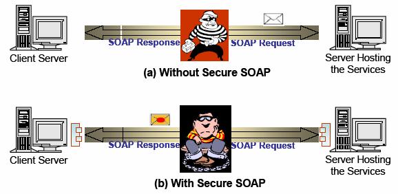
3.3 Decoupled User Access Management
User Access Management (UAM) has been implemented in many forms and in a wide variety of ways, from the most basic to the most complex. At the most simple form, the functionality would include username and password support. On the end of the scale, it would include functionalities like distributed access management, replication capabilities and fine-grain controls just to name a few.
In this specification, the goal is to provide a set of Functional Element that can be used as building blocks for UAM, and can be extended when the need arises. It is provided as a decoupled building blocks consisting of four Functional Elements, namely User Management, Group Management, Role & Access Management and Phase & Lifecycle Management, as illustrated in Figure 21. These Functional Elements can be used in a variety of combinatorial forms, and some of these examples include:
· User Management only, or
· User Management and Group Management, or
· User Management and Role & Access Management, or
· User Management, Group Management and Role & Access Management, or
· All the four Functional Elements in tandem
On the same token, any of the Functional
Elements can be replaced with similar functionality third party web services.
As these services are designed to be in a web service environment, each of them
also supports the concept of namespace. This namespace provision enables each
of the Functional Elements to be used as web services that can be accessed by
multiple organisations or to cater for users from different domains. With this,
access control for example, can be defined for multiple domains without
corruption or interferences problems.
|
|
|
Figure 39: User Access Management via Functional Element |

3.4 Single-Sign-On for Distributed Services (Applications)
In a SOA world, it is very likely that services for a composite application can be potentially made up of multiple 3rd party services from different application domains. It is also very likely that each of these domains will require authentication of the user separately. However, it is not user friendly to enforce re-authentication as the user moves from one domain to another. Using the Identity Management Functional Element, with the potential combination of Secure SOAP Functional Element and other user access management Functional Elements like User Management, a solution for such an environment can be put together to enable Single-Sign-On. In this scenario of use, a Circle of Trust between different application domains can be established using the Identity Management Functional Element, and the exchanges between these domains can be secured using the Secure SOAP Functional Element. Access and authentication to individual domains remain the purview of the distributed applications, and can potentially also leveraged on the Decoupled User Access Management scenario detailed in section 3.3.
|
|
|||
Figure 40: User Access Management via Functional Element |